DX8200 CONTROLLER
QUICK GUIDE
11
Minimum Code Height for Omnidirectional Reading (mm)
Conveyor Speed (m/s) 0.5 1 1.5 2 2.5 3
0.25
8 9 11 13 15 17
0.30
9 10 11 14 16 18
0.33
9 10 12 14 16 18
0.38
11 12 13 15 17 19
0.50
13 14 15 16 18 20
0.60
15 16 17 18 19 22
EAN 8-13, UPC-A
Code Resolution (mm)
1.00
24 25 26 27 28 29
Table 5
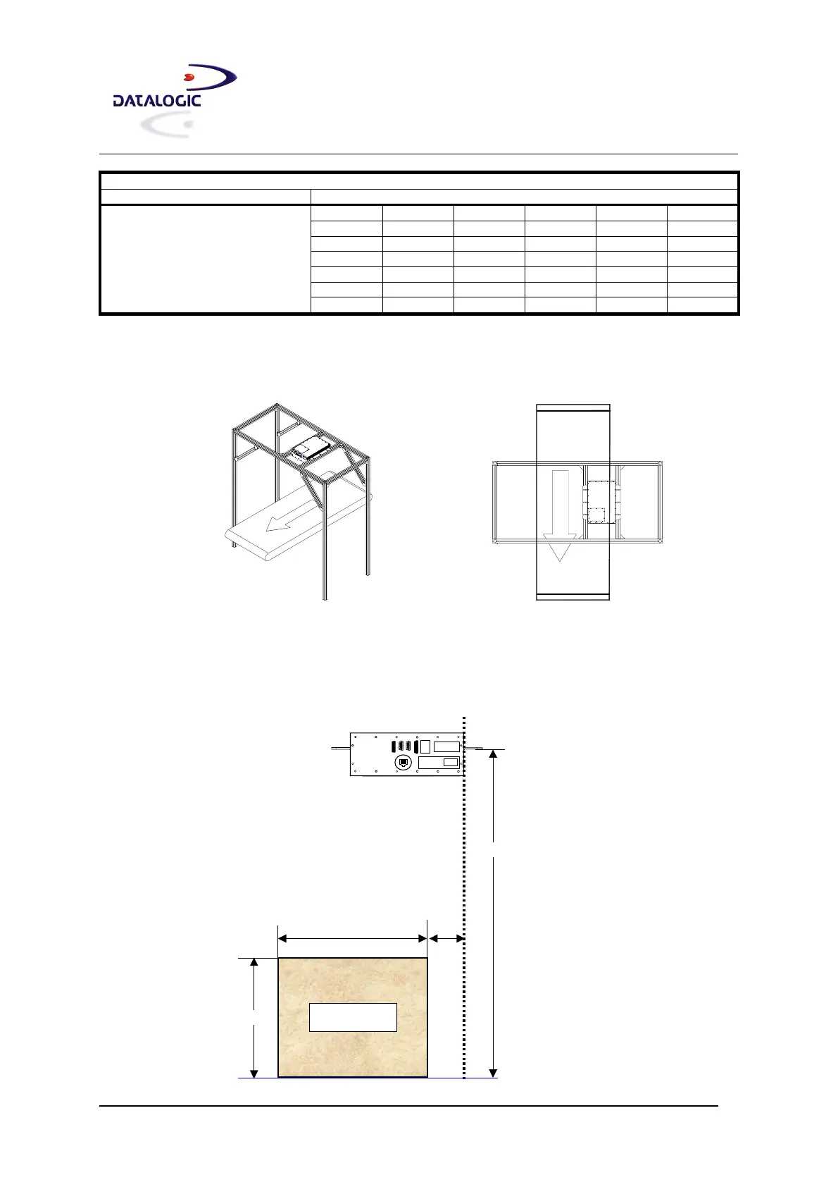
The following drawings show the relative position of the scanner with respect to the conveyor movement and the
reading diagrams given refer to this application layout.
Reading Diagrams:
The following general drawing can be used with the table below to define the Reading Area of the various scanner
models and code densities.
DX8200 Controller 201X
1100
Dimensions given in mm
CONVEYOR PLANE
Reading Area
DOF
400
120
500
FW
Ref.
Code Resolution = 0.25 mm
 Loading...