19-PIN CONNECTOR ELECTRICAL CONNECTIONS
75
5
5.7 ETHERNET INTERFACE (MATRIX 400 XXX-010 MODELS ONLY)
The Ethernet Interface can be used for TCP/IP communication with a remote or local host
computer by connecting the reader to either a LAN or directly to a host PC.
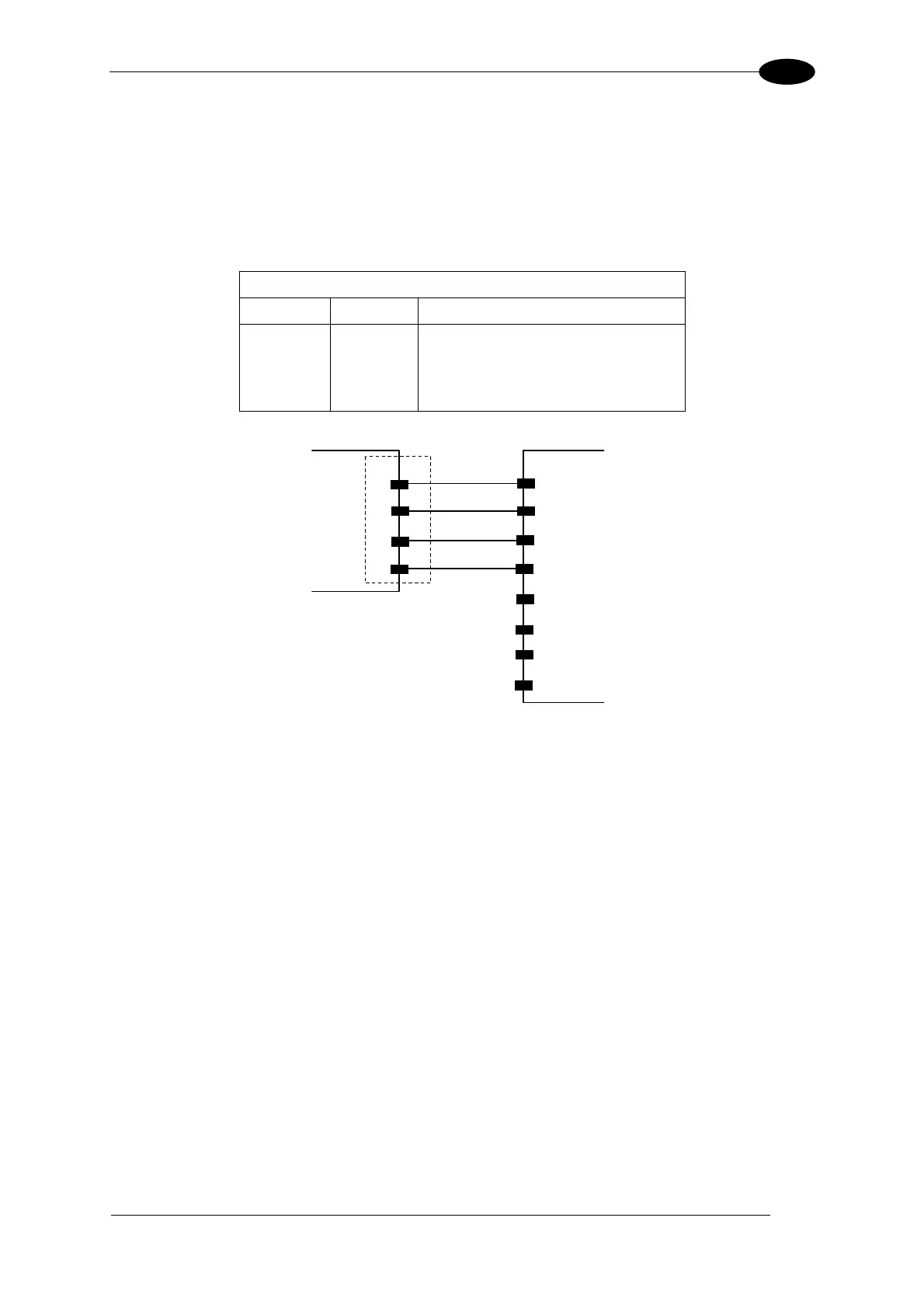
The following is an example of a connection to a LAN using a CAB-ETH-M0x straight
through cable:
M12 D-Coded Connector Pinout
Pin Name Function
1 TX+ Transmitted data (positive pin)
2 RX+ Received data (positive pin)
3 TX- Transmitted data (negative pin)
4 RX- Received data (negative pin)
MATRIX
3
4
2
1
TX-
RX+
TX+
RX-
LAN
4
2
6
3
1
5
7
8
TX-
RX+
TX+
RX-
M12
D-coded
RJ45
Figure 87 - Straight-Through Cable
For direct connection to a PC use the CAB-ETH-M0x cable with a crossover adapter.
On the Matrix 400™ Ethernet interface the following communication channels are available:
Data Socket
Image Socket
WebSentinel Socket
Image FTP Client
HTTP Server
Email Client
Ethernet IP
For further details refer to the Ethernet Folder in the VisiSet™ Help On Line and to the
"Matrix Ethernet Service Guide.pdf" document provided as supplementary documentation.
 Loading...