EasyManuals Logo

Datalogic Matrix 400 Reference Manual

Datalogic Matrix 400
142 pages
To Next Page IconTo Next Page
To Previous Page IconTo Previous Page
Page #91 background imageLoading...
Page #91 background image
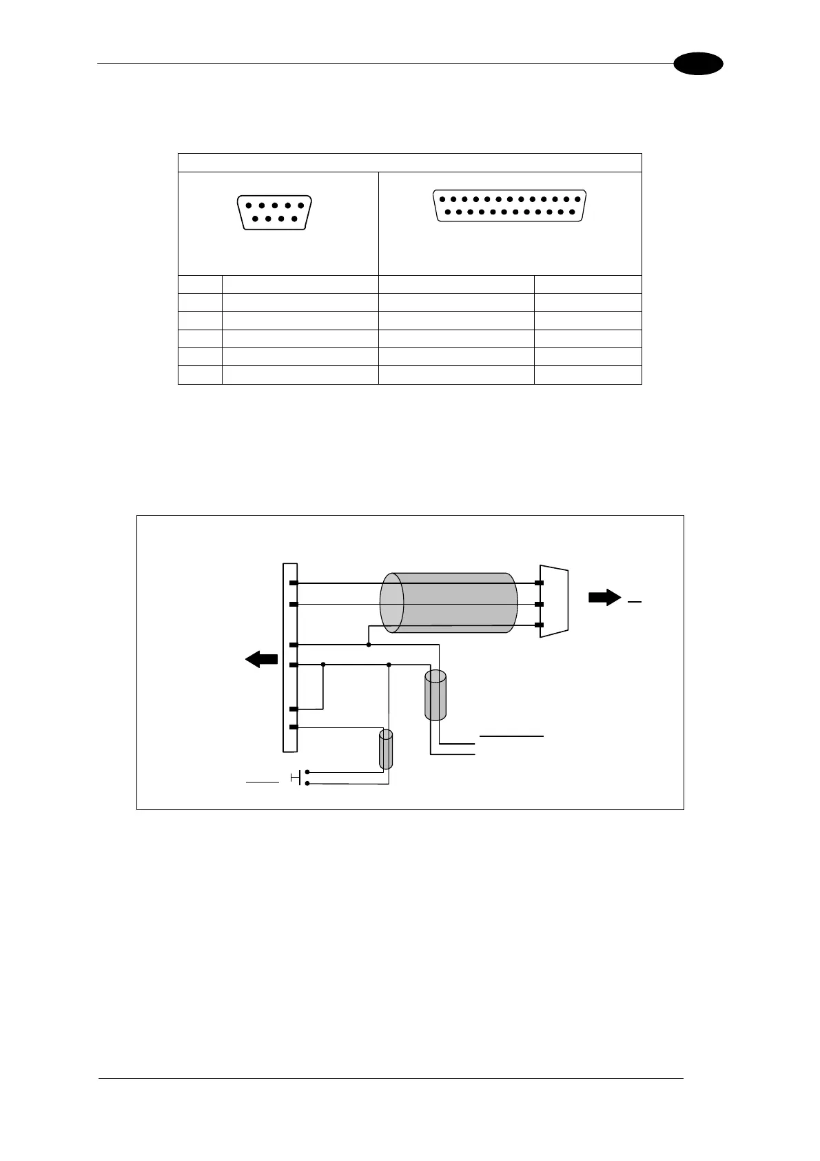
19-PIN CONNECTOR ELECTRICAL CONNECTIONS
81
5
5.10 USER INTERFACE
RS232 PC-side connections
1
5
9 6
9-pin male connector
13
2514
1
25-pin male connector
Pin Name Pin Name
2 RX 3 RX
3 TX 2 TX
5 GND 7 GND
7 RTS 4 RTS
8 CTS 5 CTS
How To Build A Simple Interface Test Cable:
The following wiring diagram shows a simple test cable including power, external (push-
button) trigger and PC RS232 COM port connections.
M16 19-pin female
S
RX
TX
O
Matrix 400™
A
L
Vdc
GND
9-pin D-sub female
GND
TX
RX
PC
2
3
5
B
I1A
Power Supply
Power GND
VS (10 – 30 VDC)
Trigger
I1B
C
Figure 99- Test Cable for Matrix 400™

Table of Contents

Other manuals for Datalogic Matrix 400

Questions and Answers:

Question and Answer IconNeed help?

Do you have a question about the Datalogic Matrix 400 and is the answer not in the manual?

Datalogic Matrix 400 Specifications

General IconGeneral
BrandDatalogic
ModelMatrix 400
CategoryLaboratory Equipment
LanguageEnglish

Related product manuals