19-PIN CONNECTOR ELECTRICAL CONNECTIONS
79
5
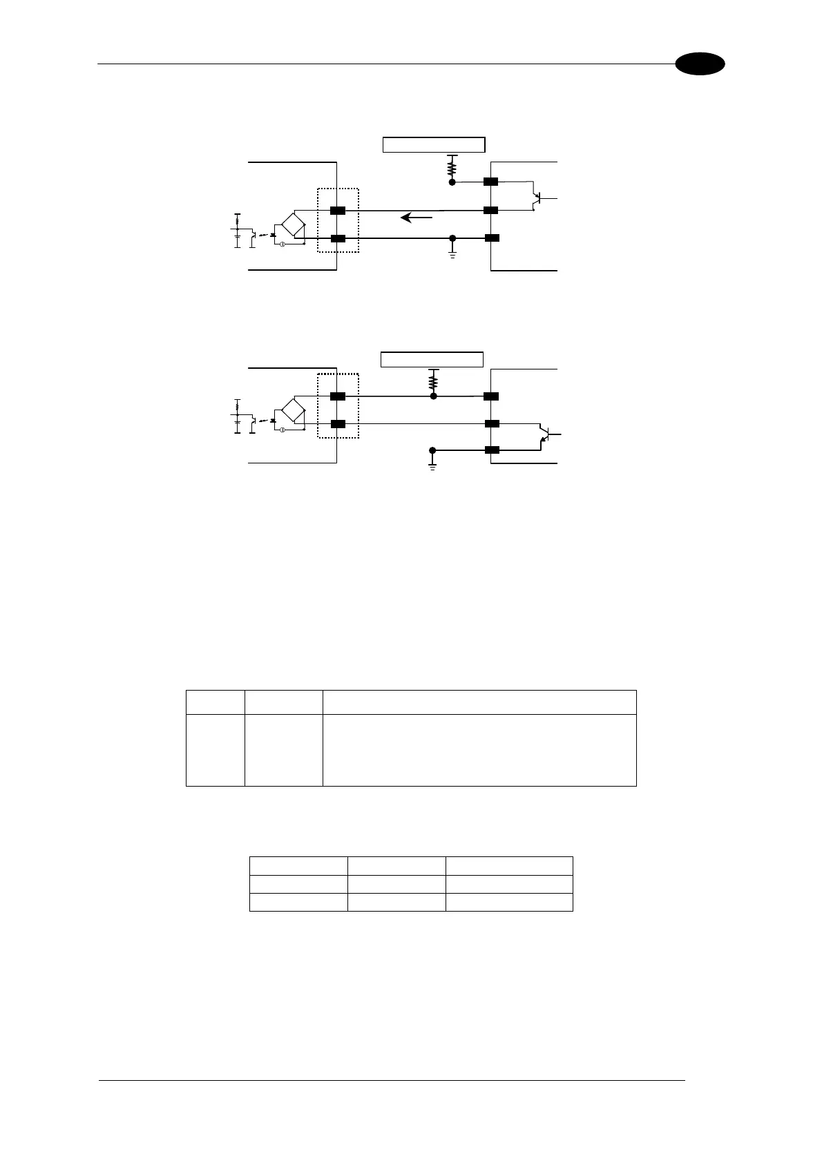
INPUT 2 CONNECTIONS USING EXTERNAL POWER
Matrix 400™
INPUT DEVICE
Vext 30 Vdc max.
D
E
V
CC
~
~
+
-
V
Signal
I2A
I2B
I
in
Figure 95 - Input PNP Using External Power
Matrix 400™
INPUT DEVICE
Vext 30 Vdc max.
D
E
Signal
V
V
CC
~
~
+
-
I2A
I2B
Figure 96 - Input NPN Using External Power
5.9 OUTPUTS
Two opto-coupled general purpose outputs are available on the M16 19-pin connector. The
meaning of the two outputs Output 1 and Output 2 can be defined by the user. They are
typically used either to signal the data collection result or to control an external lighting
system.
The pinout is the following:
Pin Name Function
H O1+ Configurable digital output 1 - positive pin
F O1- Configurable digital output 1 - negative pin
G O2+ Configurable digital output 2 - positive pin
I O2- Configurable digital output 2 - negative pin
The electrical features of the two outputs are the following:
OUTPUT I
Load
V
Out
Open 0 mA 30 Vdc Max
Closed 10 mA 1.8 Vdc Max
P
D
= V
Out
I
oLoad
= 170 mW Max.
By default, Output 1 is associated with the Partial Read and No Read events, which activates
when the code(s) signaled by the external trigger are not decoded, and Output 2 is
associated with the Complete Read event, which activates when all the selected codes are
correctly decoded.
 Loading...