CONNECTIONS
28
SH4 STANDARD MUTING
SH4-X-XXXX-SM-8-5
RECEIVER
DUAL CONNECTOR
EMITTER
DUAL CONNECTOR
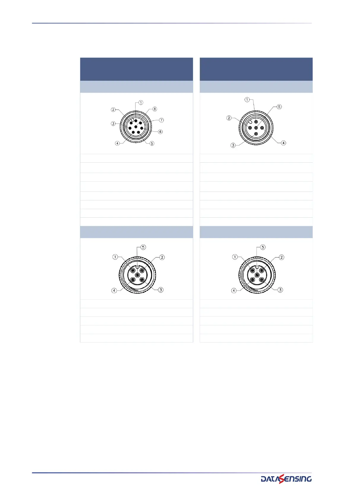
RX M12 MALE 8 PIN TX M12 MALE 5 PIN
1 - RESET/RESTART (white) 1 - 24V (brown)
2 - 24V (brown)
2 - TEST (white)
1
1. Pin 2-2 of male-female connector are internally short-circuited thus should be connected one-
side only
3 - OVR1 (green) 3 - 0V (blue)
4 - EDM (yellow)
4 - CODE (black)
2
2. Pin 4-4 of male-female connector are internally short-circuited thus should be connected one-
side only
5 - OSSD1 (grey) 5 - COM (grey)
6 - OSSD2 (pink)
7 - 0V (blue)
8 - OVR2(red)
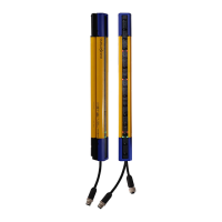
RX M12 FEMALE 5 PIN TX M12 FEMALE 5 PIN
1 - 24V OUT (brown) 1 - 24V OUT (brown)
2 - MUT2 (white) 2 - TEST (white)
3 - 0V OUT (blue) 3 - 0V OUT (blue)
4 - MUT1 (black) 4 - CODE (black)
5 - COM (grey) 5 - NOT CONNECTED (grey)