UM-0085-B09 DT80 Range User Manual Page 335
RG
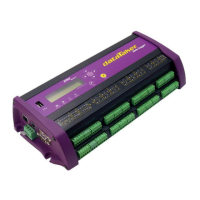
DO1 – Driving a Relay
Loads of up to 100mA @ 30V dc can be directly driven by the open-drain digital outputs 1D-4D (1D-3D for DT81/82E).
Note that inductive loads such as relays should include a reverse diode to limit transients, as shown below.
The power supply for the load can be an external supply, or you can use the power outputs provided on the DT85/DT80
Series 2-3 (12V or PWR OUT). On series 4 models along with 12V also the 5V power output is abailable with current
load up to 300mA. Both power outputs are referenced to DGND.
Figure 157: Wiring for driving an external relay
energise relay
DO2 – Driving a LED
A LED indicator can also be directly driven by the open-drain digital outputs 1D-4D (1D-3D for DT81/82E).
The value of the current limiting resistor should be chosen to suit the supply voltage and LED characteristics. A value of
1kΩ will set a LED current of about 10mA if a 12V supply is used. For 5V power supply output 470R current limiting
resistor would be sufficient.
Figure 158: Wiring for driving an external LED
turn LED on
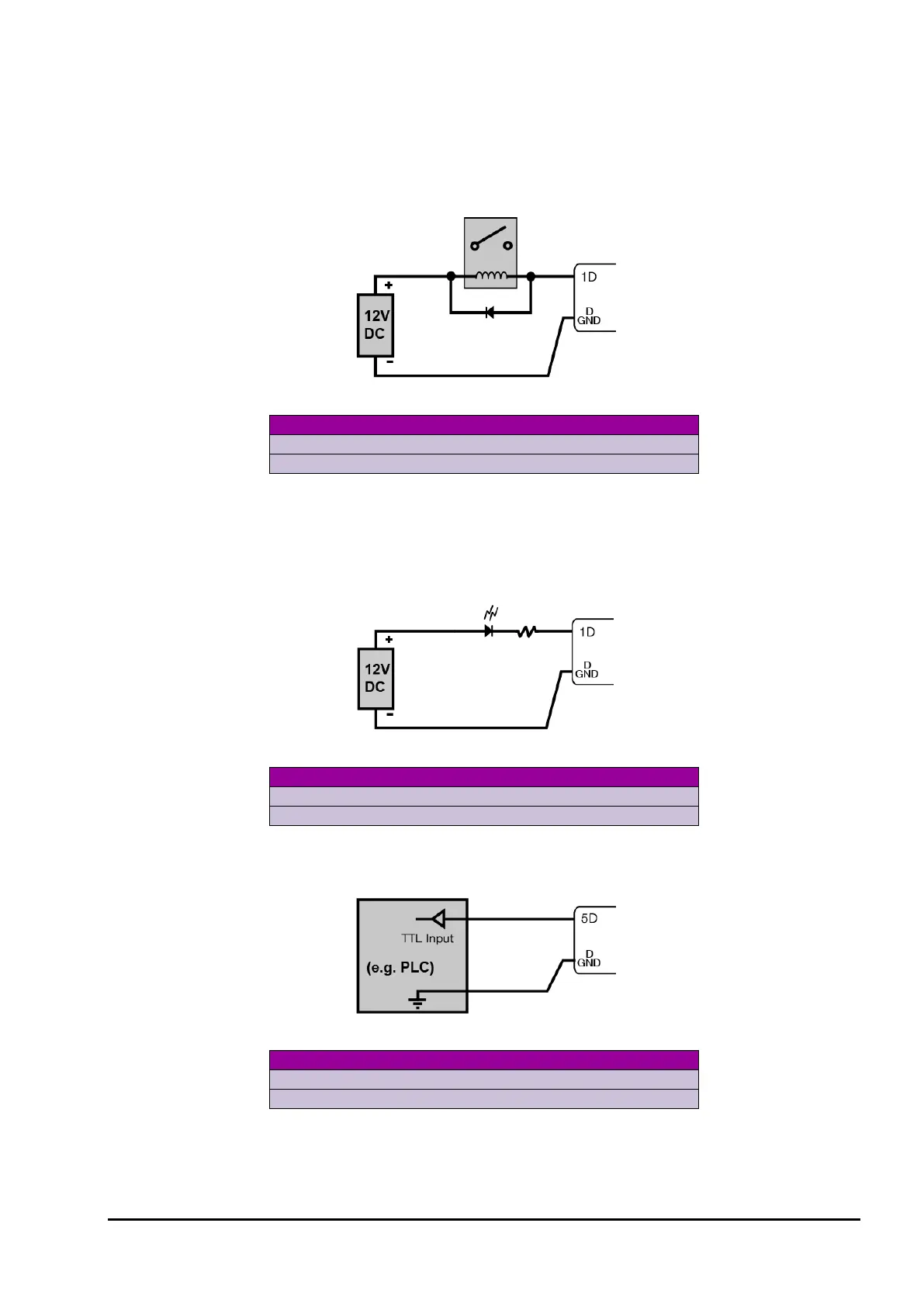
DO3 – Logic Outputs
Any of the digital outputs (1D-8D) can be used to drive a TTL-compatible logic input, as shown below
Figure 159: Wiring for driving external logic
set output low