UM-0085-B09 DT80 Range User Manual Page 385
RG
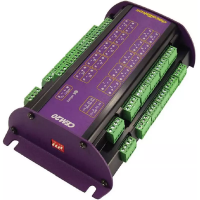
CEM20 Specifications
Interfaces
• Power/Control inputs: 12Vdc, ground, serial data, serial clock (from logger or previous CEM20)
• Power/Control outputs: 12Vdc, ground, serial data, serial clock (to next CEM20)
• Analog output: (to logger channel corresponding to CEM20 address)
• 20 x 4-wire analog inputs
Connections
• Max total cable length between data logger and furthest CEM20: 100m
• Max supported CEM20 units per data logger:
DT80 (Series 2 or later): 5
DT85 (Series 2 or later): 16
DT81/ 82: none
Sampling
• Type: Relay multiplexer
• Maximum Input Voltage: 30Vdc
• Maximum Sampling Speed: 15Hz
• Internal RTD reference junction sensor for thermocouple measurements
System
• Status LED: Sample activity
• Address Selection: 4-way DIP switch. Address 1-15
Power Supply
• Recommended: Logger’s switched 12V output
• Alternative: External regulated 12Vdc ± 5%
Power Consumption
• Sampling: 0.36W (12V 30mA)
• Idle: 0.01W (12V 1mA)
Note: In most cases idle power consumption will be zero because the DT80's 12V output will be turned off when not sampling
Physical and Environment
• Construction: Powder coated steel and anodized aluminium
• Dimensions: 180 x 100 x 50mm
• Weight: 0.55kg
• Temperature Range: -40°C to 70°C
• Humidity: 85% RH, non-condensing
Accessories Included
• Analog and power/control cables for connection to the DT80


 To Next Page