PSX-AR Manual Rev: P Software Rev: N
10
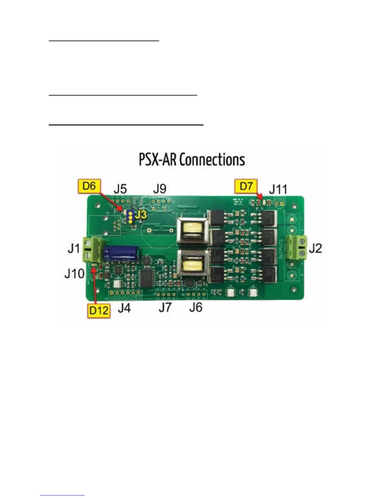
J9 Dual Coil Switch Machine Option
• J9-1 Switch Coil Output [-]
• J9-2 Switch Common [+]
• J9-3 Switch Coil Output [-]
• J9-4 Switch Common [+]
• Either J9-2 or J9-4 may be used for the common of three wire switch machines
J10 DCC Power In Remote LED Indicator Output
• J10-1 + [anode] DCC Power In LED Remote [copies D12]
• J10-1 - [cathode] DCC Power In LED Remote [copies D12]
J11 Track Power On Remote LED Indicator Output
• J11-1 + [anode] Track On LED Remote [copies D7]
• J11-2 - [cathode] Track On LED Remote [copies D7]
G. Terminal Functions
J1 – DCC power input connections from the DCC booster.
J2 – DCC track power output terminal from the PSX-AR circuit breaker to the track.
J3 – Programming & Operation jumper. Normal operating configuration is when the jumper
is in the J3-2 to J3-3 position. Place the jumper in the J3-1 to J3-2 position to enter
programing mode.
J4-1 and J4-2 are the inputs for the photocell detector used for the stopping function and/or
the block occupancy function. Note: Be sure there is sufficient light above the cell to trigger
the circuit. The photocell sensitivity is calibrated to the local light intensity each time the
photocell is armed. You can order the photocell sensor through Tony’s Train Exchange.