12
3.6 EVAPORATOR FROST PATTERN
Checking the evaporator frost pattern is a good way to quickly diagnose simple sealed system problems. This can
be done by allowing the unit to run (at least 10 minutes) with the door open for at least 5 minutes. This will help
speed up the normal frosting of the evaporator plate. By visually inspecting the evaporator and feeling it with your
hands, you will see and feel frost across the plate. It is absolutely necessary for the frost to cover the entire evapora-
tor plate. This will ensure the system has been charged to its specified amount or does not have a leak. A partial
frost pattern may lead to excessive run times or even 100% run mode. This is because the frost does not reach the
area of the evaporator thermistor thus it does not sense the temperature required to cycle the unit off.
3.7 PRESSURE AND TEMPERATURE
There are a couple of ways to measure temperature of the evaporator plate:
Use a thermocouple to measure the temperature of the evaporator plate. The thermocouple must be secured to the 1.
evaporator when taking the measurement.
If it has been determined that there is proper contact between the thermistor and evaporator plate, the thermistor 2.
resistance value can be corresponded to the temperature (see Table C in Section 5.2, Thermistors for values).
NOTE: The temperature and pressure reading must be taken while the unit is on and running. Use gage pressure read-
ings from the compressor’s process tube (low side) access valve.
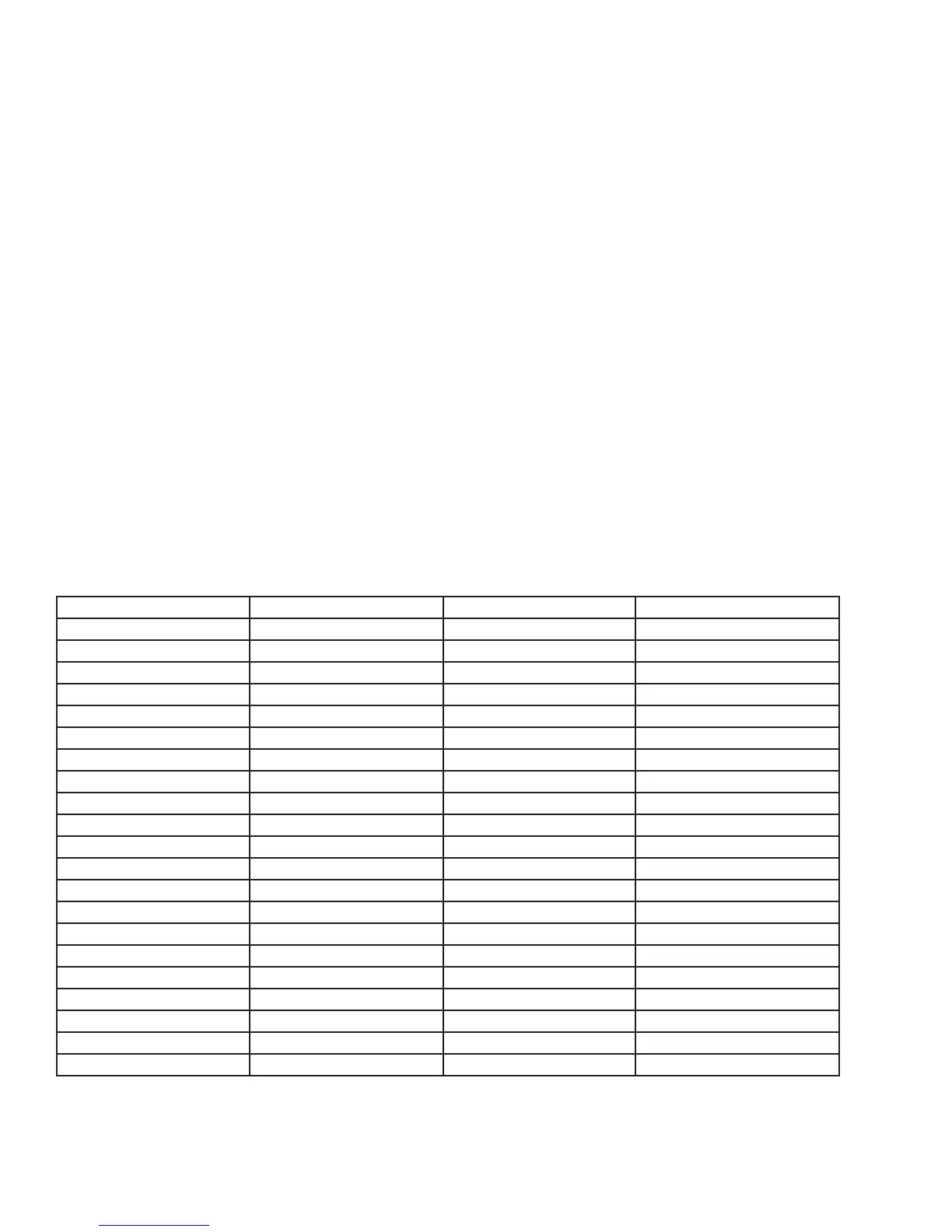
Table B: Refrigeration Temperature-Pressure Chart for R-134a
Degrees F Pressure (psi) R-134a Degrees F Pressure (psi) R-134a
-12 1.1 36 31.3
-8 2.8 38 33.2
-4 4.5 40 35.1
0 6.5 42 37.0
2 7.5 44 39.1
4 8.5 46 41.1
6 9.6 48 43.3
8 10.8 50 45.5
10 12.0 52 47.7
12 13.1 56 52.3
14 14.4 60 57.5
16 15.7 64 62.7
18 17.0 68 68.3
20 18.4 72 74.2
22 19.9 76 80.3
24 21.4 80 86.8
26 22.9 84 93.6
28 24.5 88 100.7
30 26.1 92 108.2
32 27.8 96 116.1
34 29.5 100 124.3
Pressure will vary depending upon the ambient temperature and current stage of operation for the unit. For example,
the unit will have pressure between 0 and 5 psi just before entering the o cycle. Normal running pressures on the low
side will average 5 to 10 PSI.
SEALED SYSTEM