15
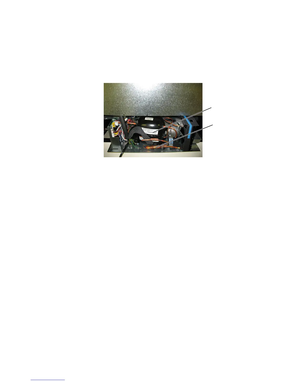
4.2 COMPRESSOR
The compressor is the heart of the refrigeration system (see Figure 4.4). However, it relies on other parts of the system to function.
Make certain that the other parts of the system are functioning correctly before determining that the compressor is faulty.
Figure 4.4
Compressor
Drier
The following should be observed before concluding the compressor is faulty:
Low high side pressures, warm evaporator plate, cool condenser coil, or little or very low current draw from the unit will indi-1.
cate a faulty compressor.
Check for continuity between the compressor terminals and the shell of the compressor. If continuity is found, the compres-2.
sor is faulty and will need to be replaced.
Check for resistance between all compressor terminals. The resistance will vary from terminal to terminal and from compres-3.
sor to compressor due to age and use. If no resistance is found, the compressor is faulty and will need to be replaced.
Removing the Compressor:
Disconnect power to the unit.1.
Remove the back panel and lower shroud (see Figure 4.1).2.
Remove the screws that hold the baseplate to the chair frame of the unit and slide out the mechanical baseplate (see Figures 3.
4.2 and 4.3).
Install sealed system access valve(s) and recover refrigerant. After recovering, be sure to cap o the access valve(s) to prevent 4.
contamination of the system.
Remove the cap from the rear of the compressor to expose the starter and overload (see Figures 4.5 and 4.6).5.
Disconnect the PTC starter and overload from the compressor by pulling o. Disconnect the wires from the starter and over-6.
load.
Un-braze and remove capillary tube from drier assembly (see Figure 4.4).7.
Un-braze and remove suction line at compressor (see Figure 4.7).8.
Un-braze high side line from the compressor going to the condenser (see Figure 4.7).9.
Remove compressor by removing the three lock nuts on the mounting plate of the compressor (see Figure 4.7). Lift the com-10.
pressor o of the carriage bolts.
SEALED SYSTEM