16
Installing the Compressor:
Install the four rubber grommets in the bottom of the new compressor and install the three sleeves where the carriage bolts 1.
will be located. Mount the new compressor and install the three washers and lock nuts and tighten to 45 in-lbs. DO NOT
REMOVE THE RUBBER PLUGS AT THE TUBE STUBS ON THE COMPRESSOR AT THIS TIME.
Install and braze new drier assembly to condenser. Then install and braze capillary tube to drier. Remove the plug for the 2.
high side line to condenser. Install and braze the line to the compressor.
Remove the plug for the process tube on the compressor. Install and braze process tube. Be sure to cap o end to prevent 3.
any contamination.
Remove the plug for the suction line on the compressor. Install and braze the suction line from the evaporator. BE SURE TO 4.
ALSO REINSTALL THE SUCTION LINE AND TUBING HARNESS INSULATION TUBES.
Reinstall the PTC starter and overload and wire according to the wiring diagram (see page 28, Wiring).5.
Reinstall the compressor cap.6.
Reinstall the screws that secure the baseplate to the chair frame of the unit. Be sure to fasten down the ground wire to the 7.
baseplate.
Charge the unit (see Section 3.8, Re-charging).8.
Reinstall back panel and lower shroud to complete installation.9.
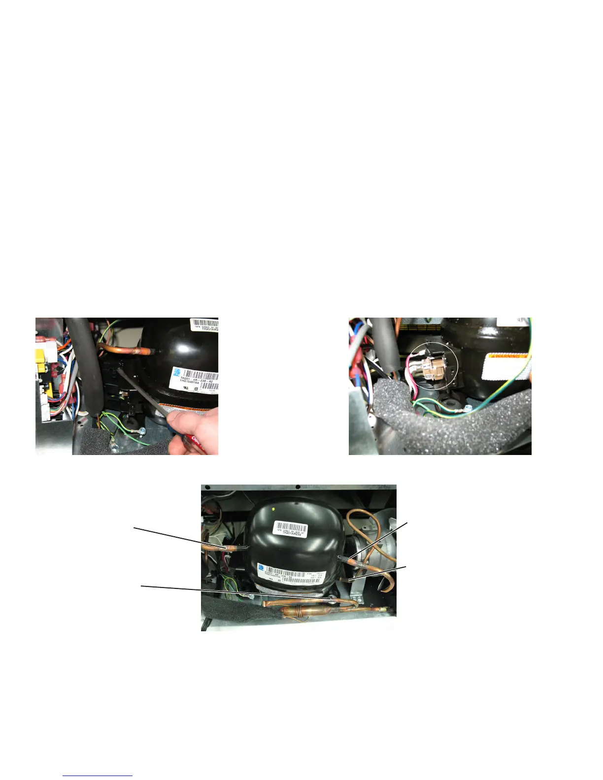
Figure 4.5 Figure 4.6
Figure 4.7
Process tube
High side tubing going to the
condenser.
Suction line tubing going to the
evaporator.
Compressor lock-nut
SEALED SYSTEM