L O O K
Operating instructions and warnings
only for qualified personnel
10
4.5 Instructions for risk-free operation
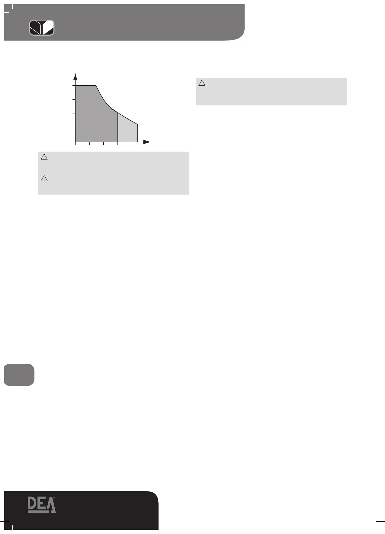
WARNING With not self-locking models, with same leaf
length, reduce of 1/3 the door admissible weight compared to
what indicated in “Length-weight” chart.
WARNING In case the leaf is more than 2 m long or in
case you use not self-locking models, an electric-lock must be
installed to hold the gate in closing position.
4.5.1 Installation, assembly and disassembly
The following operations are essential to the correct laying
of the product:
• Thecarefuldefinitionoftheentireautomaticopeninglayout
(see also “6 Complete Closing Assembly”); in particular,
after carefully assessing the characteristics of the supports
and the gate, the attachments must also be designed and
positioned according to the angle of opening desired (see
F2, F3 Page 38-39).
• Verify that any mechanicalfeature of the gate are in good
conditions and allows a safe automation. Moreover check the
balancing, gate has to correctly and freely move on its hinges
and once stopped in any position, it has to stay blocked.
The fastening of the attachments must be performed with
extra care on both pillars and gate, here are the dimensions
suggested by DEA SYSTEM (see F3 page 39). Pay extra at-
tention to the horizontal alignment between rear fastening
support and front one.
General considerations to establish the installing dimen-
sions:
• ThesumofA+Bfor90°openingsisequaltoCrodrun
• A+B<Ctoincreasetheopeningangle
• AandBlowerthanwhatsuggested,involveahigherdoor
tangential speed
• If A and B are 5 cm greater than what suggested, limit
switches (if foreseen) adjustment won’t be possible
To install the operator proceed as follows:
• Weldorscrewtherearfasteningsupporttothepillar,inpre-
fixed position
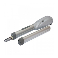
• ApplyLOOKtotherearfasteningsupport
• Executethemanualunlockingoperation(seefollowingpara-
graph) and take off completely the rod
• LockLOOKagainandturntherodhalfway
• FixthefrontalfasteningsupporttoLOOKrod
• Weldorscrewthefrontalfasteningsupporttothedoor(with
door completely closed), by keeping LOOK in an horizontal
position
• Unlock again and make a complete opening and closing
cycle, this is to check that gate moves freely and without any
hindrance (with cover rod)
WARNING In order to make the structure sufficiently strong,
reinforcement plates to be fixed to attachments may be ne-
cessary
WARNING Grease pins before assembly
• Forversionsthatforeseethecoverrod,adjustlimitswitches
while assembling (see page 34)
4.5.2 Starting and adjustment
WARNING During the connection phase, fasten the
electric cables with appropriate clamps near the terminal
boards and, when possible, unsheathe the cables to avoid
they are too long.
LOOK must be electrically connected to a DEA SYSTEM con-
trol panel; refer to the instructions provided for such device for
further information.
For LOOK wiring, proceed as follows (se also page 33):
24V/230V standard version
• RemovetheplasticcoverpositionedunderLOOK
• Openoneoffourshapedholesandchoosewherethecable
exit has to be
• Introducethecableclampandfixitbyitsnut
• Insertthepowersupplycableintotheclamp(comingfrom
the control panel): A quadrupole cable suitable for external
applicationswitha4x1mm²section(or2x1,5mm²for24V
operators)(minimum H05RN-F type) coming directly from
the control panel (without any connection and shunt box)
and supplied by the installer;
WARNING: do not remove too much outer insulation on the
power supply cables.
• Executemotorconnectionsasindicated:
24/230V version with limit switches
• Fortheoperatorpowersupplyconnectionfollowtheinstruc-
tions of the basic version.
• Openasecondholeintheplasticcoverandapplythese-
cond provided cable clamp (a reduced M16).
• Usea3x0,75mm²cable(notsupplied)andlookatthedia-
gram at page 11 for a correct limit switches wiring to the
control panel.
230V version with encoder
• Fortheoperatorpowersupplyconnectionfollowtheinstruc-
tions of the basic version.
• Openasecondholeintheplasticcoverandapplythesecond
provided cable clamp (a reduced M16).
• Usea 3x0,5mm² LiYY (DEAart.182021)to be ordereda
part) and follow the diagram on page 11 to correctly connect
the encoder to the control board.
• Usethecablewithpanduitconnectorsuppliedinthekittocon-
nect the previously used cable to the control board, by using the
clamp 3 “poli” inside the package.
WARNING: Maintain the ground conductor at a major length
respect the active conductors so that, if the cable exit from its
fixing housing, the active conductors tighten up as first.
WARNING: Respect the Phase-Neutral polarity of the tension as
explained by the instructions manual of the control panels
of LOOK.
• Re-assembletheplasticcoverensuringthatanycabledonot
touch moving parts of the operator
WARNING: LOOK limit switches have been exclusively foresaw
to directly connect their inputs to the control panel and so
they are submitted to a very safety low tension. Therefore
keep a proper distance between limit switches cables and
power supply cable of 230V operator.
WARNING: while installing, maintain a proper distance between
the power cable conductors and the operator
“LENGTH-WEIGHT” chart
1 2 3 4
800
600
400
200
m
350, 351, 352, 371, 372
Kg
355, 356
373, 374