GHD
™
& Scout
™
User’s Manual
GHD
™
& Scout
™
User’s Manual
26
25/Aug/2010
• A valid target motor vehicle speed in the operational range will
always override the source of interference and will be conrmed
by the audio component. (See paragraphs 7.2.2 through 7.2.8.)
• The Doppler tone will lack the pitch and clarity component.
• Speeds are irregular.
• Speeds appear to track with the engine speeds.
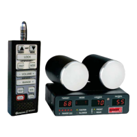
7.2.1 Angular Interference (Cosine Eect)
The cosine eect causes the system to display a speed which is
lower than the actual vehicle speed. This condition occurs when
the target vehicle’s path is not parallel to the antenna, including
conditions such as the vehicle traveling on a curve or hill.
As the angle between the beam of the antenna and the target
vehicle increases, the displayed speed decreases. Ideally, an angle
of zero (0) degrees is preferable, because the displayed speed is the
actual target vehicle speed. However, in all uses of police radar, the
radar device is always at a slight angle to the target vehicle to avoid
collisions.
Velocity
Vector
Angle
Radar
Figure 7.2.1a
An angle between the antenna and the target vehicle causes the cosine eect.
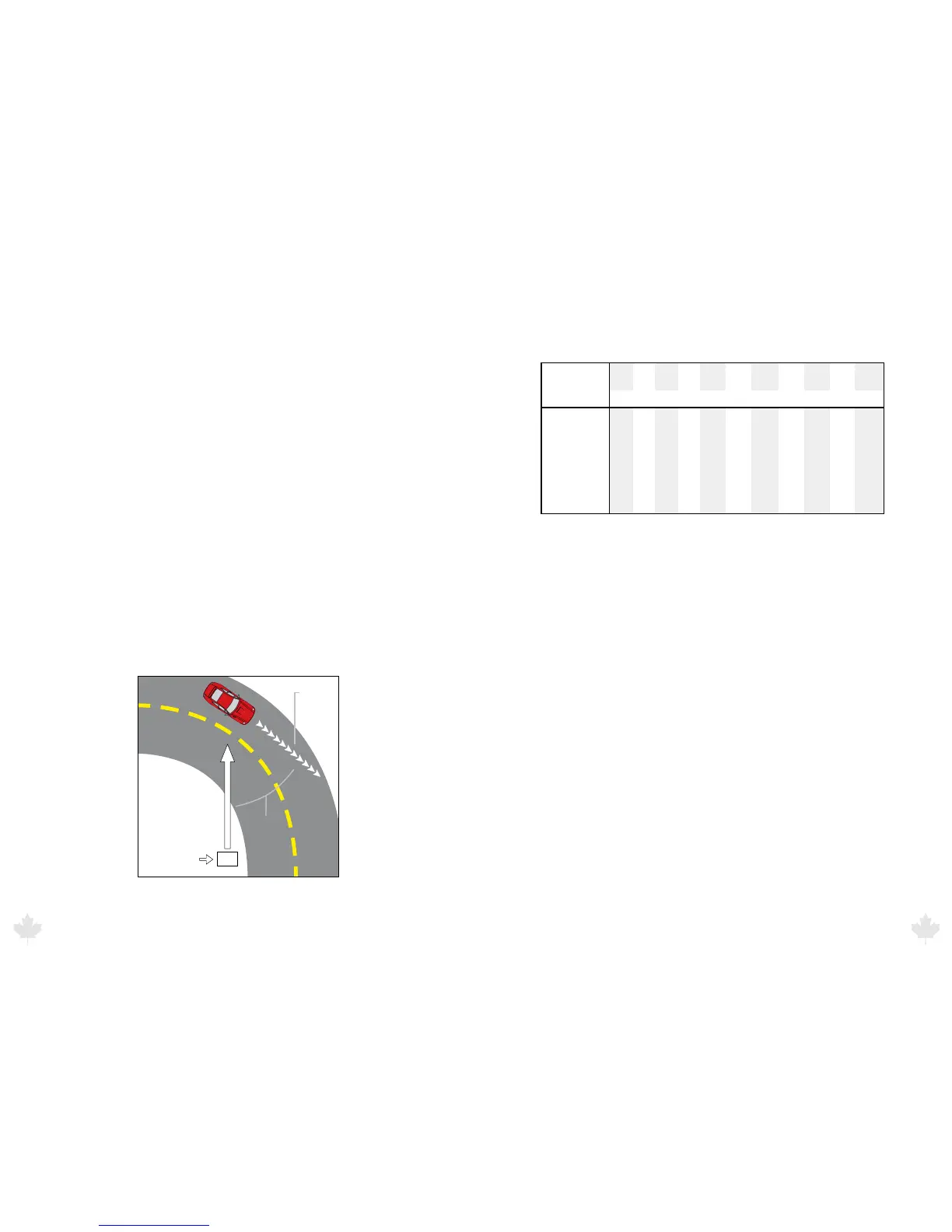
The following table shows the eect that an increasing angle has
on a displayed speed.
Horizontal Angle Degrees
Actual
Speed
0° 1° 3° 5° 10° 15° 20° 30°
Displayed speed:
45° 60° 90°
50 km/h 50 49 49 49 49 48 46 43 35 25 0
65 km/h 65 64 64 64 64 62 61 56 45 32 0
80 km/h 80 79 79 79 79 77 74 69 56 40 0
90 km/h 90 89 89 89 88 86 84 77 63 45 0
100 km/h
100
99 99 99 98 96 93 86 70 50 0
110 km/h
110 109 109 109 108 106 103
95 77 55 0
Table 7.2.1b
Actual and displayed speeds at dierent antenna-to-target angles.
Small angles (less than 10°) have little eect on accuracy. As the
angle increases, the displayed speed decreases. At 90°, the target
speed is 0—grossly incorrect. Cosine Eect will always result in a
target speed being displayed that is less than the actual speed of
the moving motor vehicle, which will always be advantageous to
the motorist.
7.2.2 Fan Interference
Fan interference is the most common form of interference that you
are likely to experience. It is caused when the radar measures the
speed of the vehicle blower fan. Changing the fan speed causes a
proportional change in the display speed.
7.2.3 Electromagnetic Interference (EMI)
Operating electric motors may produce EMI. With the DSP
algorithms the GHD and Scout has eliminated this.
7.2.4 Feedback Interference
When the radar beam is directed at computer screens, streetlights,
and other electronic devices, it can display spurious speeds. To
correct the interference, relocate the radar gun antenna.
25/Aug/2010
27