SI-3
™
User’s Manual
7
3. Getting Started
3.1 Introduction
The SI-3™ is a radar specically designed to measure speeds and
export that speed information as RS232 data via the attached
serial cable. This allows the SI-3™ to be used for a wide range
of applications such as Radar Speed Trailers, trac speed data
collection (when used with the Decatur EZ Stat™ data logger) or
other uses where speed monitoring is desired. The SI-3™ comes
with a Programming disk that allows the user to congure certain
parameters of the SI-3™ for specic applications. Refer to Chapter 4
for conguration information. Additionally, a Radar Monitor program
is also available that allows you to display speed information on your
computer and record that information to a text le for analysis.
3.2 Connecting the Serial Cable
The SI-3™ operates o of +12VDC and is equipped with a specialized
DB-9 serial connector that contains provisions for powering the unit.
When connecting the cable it is important to understand that unlike
standard RS232 serial connectors that have no +12VDC provisions
the SI-3's™ serial connector has two pins dedicated to B+ and ground
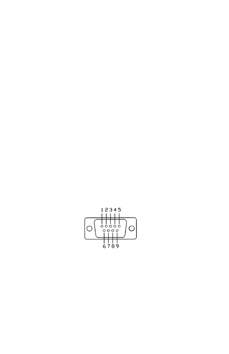
for the purpose of powering the unit. Figure 3.2 shows the pin
arrangement.
Figure 3.2
Front view SI-3™ Serial Connector
Pin 1 = +12VDC (power) (red wire)
Pin 2 = RS232 TX (white wire)
Pin 3 = RS232 RX (green wire)
Pin 4, 6 ,7 = N/C
Pin 5 = RS232 Ground (brown wire))
Pin 8 = Remote ON (blue wire)
Pin 9 = Ground (power) (black wire)