SI-3
™
User’s Manual
8
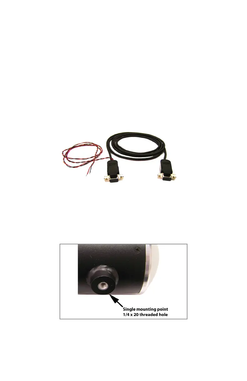
3.3 Optional Programming Cable
For conguring and testing purposes a programming cable is
available. The cable is designed with two DB-9 connectors and a
black and red wire for supplying B+ and ground to the SI-3™. One
end of the cable plugs into the serial port of a computer and the
other end into the SI-3™. The same end that plugs into the SI-3™ has a
red wire that is connected to +12 VDC and a black wire that connects
to ground. A regulated power supply can be used to supply the +12
VDC. Once the programming software is installed on the computer
then the SI-3™ can be accessed and parameters changed to meet
your application. Refer to Chapter 4 for programming information.
Figure 3.3
Optional Programming Cable
3.4 Mounting Conguration
The SI-3™ utilizes a single mounting point designed for quick, easy
installation. A standard ¼ x 20 bolt is used to mount the SI-3™ .
Figure 3.4
S785-30-0
(3 foot cable)