SF600/SF600
Plus
Serial Flash Programming solution
www.dediprog.com 18
A. Application SPI Flash supply: Vcc
Specification for the ICP Vcc pin:
- Vcc is set at 3.3V by default and can be adjusted down to 1.8V from the
software interface
- Icc max supplied = 100mA
The application SPI Flash can be supplied by two different sources:
a) by the programmer via ICP Vcc pin at 3.3V
b) by the application according to the SPI Flash specification
The SF600 and SF600Plus have been designed with a Serial diode on the Vcc to
protect against any conflict with the application Vcc.
B. SPI signals management: CS1, CS2, CLK, MISO, MOSI, DQ0-4, IO, reset/IO3
The SPI signals are used to communicate with the application SPI Flash with a high
frequency (up to 25MHZ). The frequency can be also adjusted from the software
interface. The signals are CMOS compatible and are switched in High Impedance
when not used. The SPI signals are turned in Low impedance after reset has been
driven low.
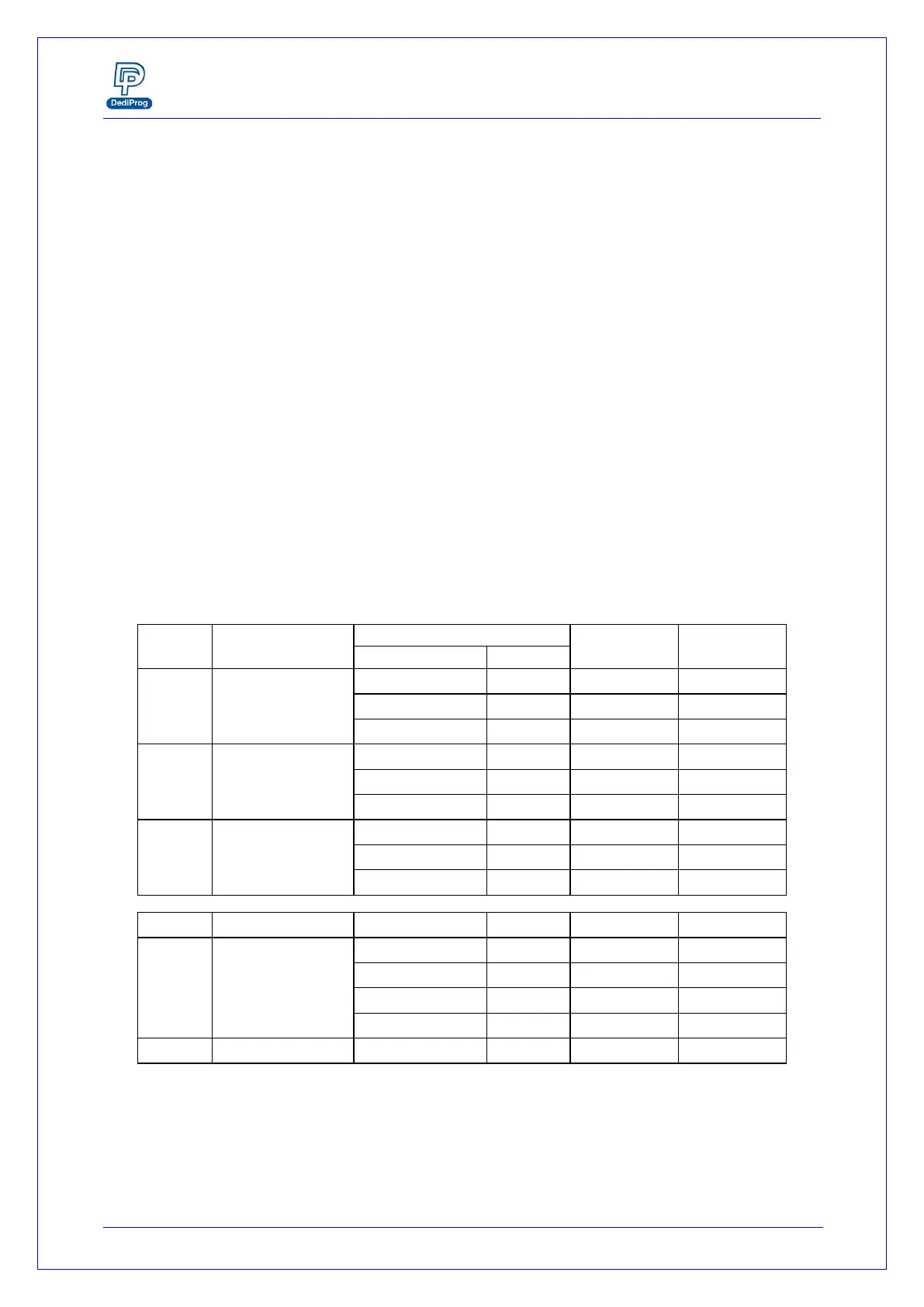
Table 7: DC specification for SPI signals and IO
High Level Output
current
This specification is relative to individual capability of one signal.
ESD high performance protection compliant with IEC61000-4-2 level 4: 15kV
(air discharge)
8kV (contact discharge)