SF600/SF600
Plus
Serial Flash Programming solution
www.dediprog.com 5
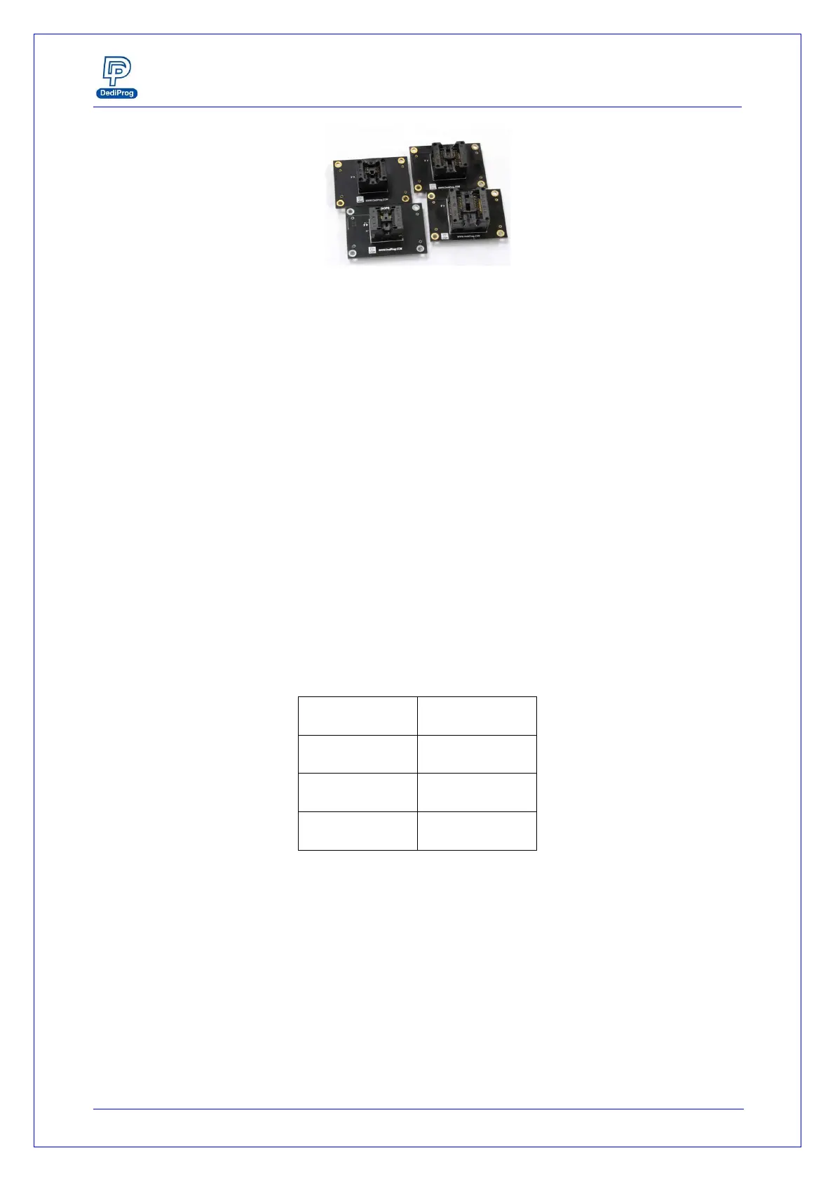
Fig 2: Socket adaptors
E. ICP Connector
ICP connector is used to connect ICP cable when executing ICP programming.
F. Operation LED
Red Led: error
Orange Led: operation on going
Green Led: pass
G. Com Port
The Com Port design is for integrating SF600/SF600Plus with customer's system. All
programmer pin outs (except 5V and NC) are default with Low status. Once
customer/system sends a High signal to trigger START which needs press and hold one
second and make the programmer working (i.e. BUSY becomes High status accordingly),
SF600/SF600Plus will also feedback PASS or FAIL result with High signal after
programming.
NOTE:
The input voltage range is between 3.5V to 6.5V which means High. The voltage cannot
over 6.5V that may cause the component damage.
Table 2: Pin Out
H. Start Button
The Start button is operations from the programmer either in USB mode. By pressing
and hold 2 seconds the start button, the SF600 and SF600Plus starts to execute the
operation procedures defined in the software Batch configuration when working in USB
mode or in the project pre-loaded to the SF600Plus when working in standalone mode.