Multi-line 2 General Guidelines for Commissioning
DEIF A/S Page 17 of 19
Adjustment hints for AGC
In many cases it is difficult to tune in the controller using load jumps (no load bank available).
When this is the situation, the manual incr/decr inputs can be used in semi-auto mode. The
inputs are digital inputs that must be configured in the utility software.
When the manual increase/decrease input is activated, the regulator is switched off and an
offset will be given to the governor or AVR. The governor/AVR outputs will be activated as long
as the manual input is activated. When the input is deactivated again, the regulation will be
switched on, and the AGC will control gen-set towards the set point.
This is an easy way to make regulation deviations during the commissioning.
Relay output adjustments
If the relay outputs are used for the speed governor/AVR, then it will be necessary to adjust the
relay minimum pulse time and the period time.
There are 2 settings: ON time, which is the shortest relay ON signal time.
PER time, which is the period time.
The shortest acceptable pulse time is depending on the reaction of the governor/AVR and
connection type. Slow reaction requires a long time pulse.
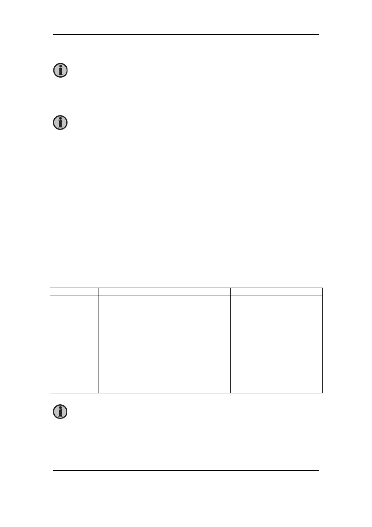
As a starting point, use the following settings for the relay ON time and relay period time:
Menu text AGC GPC/PPU/GPU Setting Comment
Governor ON
time
Menu
2251
Menu 2641 500…1000ms
Governor
period time
Menu
2252
Menu 2642 2500…5000ms It is recommended that the
period time is approximately
5*ON time.
AVR ON
Menu
2253
Menu 2643 100ms
AVR period
time
Menu
2254
Menu 2644 500ms It is recommended that the
period time is approximately
5*ON time.
It is still necessary to tune in the PI controllers.
The number of digital inputs is option dependent.
This concerns the AGC only!