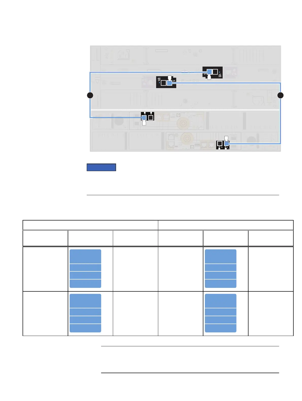
Figure 26 Example: DPE to DAE BE1 enclosure 0 (continued)
When cabling the 15-drive DAE LCC SAS ports, ensure that the cables do not overlap
behind the DAE. The illustration above demonstrates the proper method for cabling to
the DAE LCC SAS ports.
Procedure
1. Label a pair of mini-SAS HD cables using the blue labels shown here.
Expansion port cable labeling details
Primary port cable labeling details
Label part
number
Label Port Label part
number
Label Port
046-001-562
SP A SAS 1
SP A SAS 1
SP A SAS 1
SP A SAS 1
046-001-562_xx
SP A SAS 1 046-021-012
LCC A PORT A
046-021-012_xx
LCC A PORT A
LCC A PORT A
LCC A PORT A
LCC A Port A
046-003-750
SP B SAS 1
SP B SAS 1
SP B SAS 1
SP B SAS 1
046-003-750_xx
SP B SAS 1 046-021-013
LCC B PORT A
046-021-013_xx
LCC B PORT A
LCC B PORT A
LCC B PORT A
LCC B Port A
2. Connect each SP to the first optional DAE to create BE1 EA0.
Neither connector on the mini-SAS HD cable has a symbol to indicate input or
output.
Cable and power up your DAE components
56 Unity 300/300F, Unity 350F, Unity 380/380F, Unity 400/400F, Unity 450F, Unity 500/500F, Unity 600/600F
and Unity 650F Installation Guide