Cabling the first optional DAE to create back-end bus 1
Connect the first optional expansion DAE to port 1 of the DPE to create back-end bus
1 (BE1) and designate this DAE as enclosure 0 of this bus. We refer to the address of
this enclosure as BE1 EA0 (1_0).
Before you begin
To prepare for this cabling task:
l
Locate the mini-SAS HD cables to be used to connect to the newly installed
expansion DAE.
Typically these cables are 2-meters long. You use longer cables, typically 5-meters
or 8-meters, to connect enclosures located in different racks. Cables are shipped
without labels attached. The cables and ports are not colored.
l
Locate the sheet of cable labels provided.
Orient the cable connectors as described in the procedure that follows, making sure
that you do NOT connect:
l
A DAE expansion port 0 to another expansion port 0.
l
Any A-side ports to B-side ports.
Use the following illustrations to complete this cabling task:
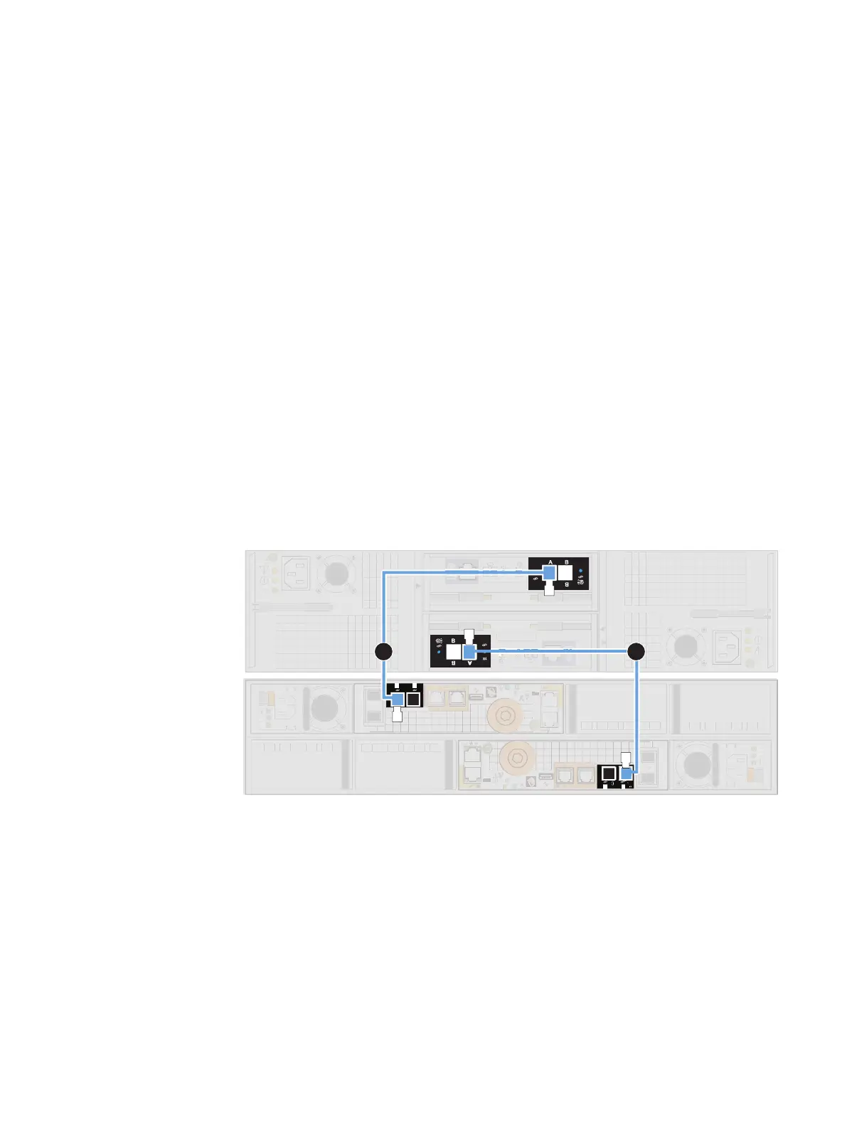
Figure 26
Example: DPE to DAE BE1 enclosure 0
DPE to 25-drive DAE SAS cabling
0 1
0
1
x4x4
x4
x4
0 1
x4
0 1
x4
12
DPE to 15-drive DAE SAS cabling
Cable and power up your DAE components
Cabling the first optional DAE to create back-end bus 1 55