Features
12 RS232/RS422/RS485 port two (congurable in the
BIOS)
Connect an RS232/RS422/RS485 cable to the Embedded Box
PC. For more information, see RS232/RS422/RS485 connector
mapping.
13 Wireless antenna port two Connect a wireless antenna to increase the range and strength of
wireless signals.
14 RS232/RS422/RS485 port one (congurable in the
BIOS)
Connect an RS232/RS422/RS485 cable to the Embedded Box
PC. For more information, see RS232/RS422/RS485 connector
mapping.
15 Wireless antenna port one Connect a wireless antenna to increase the range and strength of
wireless signals.
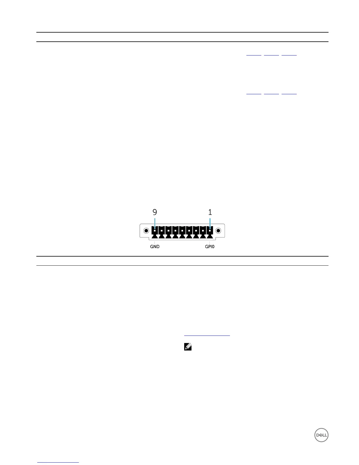
1 The GPIO-in port has 9 pins. Pin labels are GND and GP10 through GP17.
2 Connections made to these ports must use SELV circuits and the wire (26 AWG-18 AWG) must have Double Insulation (DI) or Reinforced Insulation (RI) to protect it from all
hazardous voltages. Torque the screws at 2.88 kg-cm (2.5 lb-in) to secure the wire to the connector.
3 The GPIO-in port has 9 pins. Pin labels are GND and GP00 through GP07.
4 Connections made to the GPIO-in/out port must use SELV circuits (30 Vmax) and must be protected by Double/Reinforced Insulation (DI)/(RI) from all hazardous voltages.
5 The antenna is shipped in a separate accessory box along with your Edge Gateway.
GPIO-in connector mapping
Pin
Signal Pin Signal
1 GPI0 6 GPI5
2 GPI1 7 GPI6
3 GPI2 8 GPI7
4 GPI3 9 GND
5 GPI4
Manufacturer part number ACES 59128-0093C-P01
https://acesna.com/
NOTE: This part number is for reference only and is
subjected to change.
10