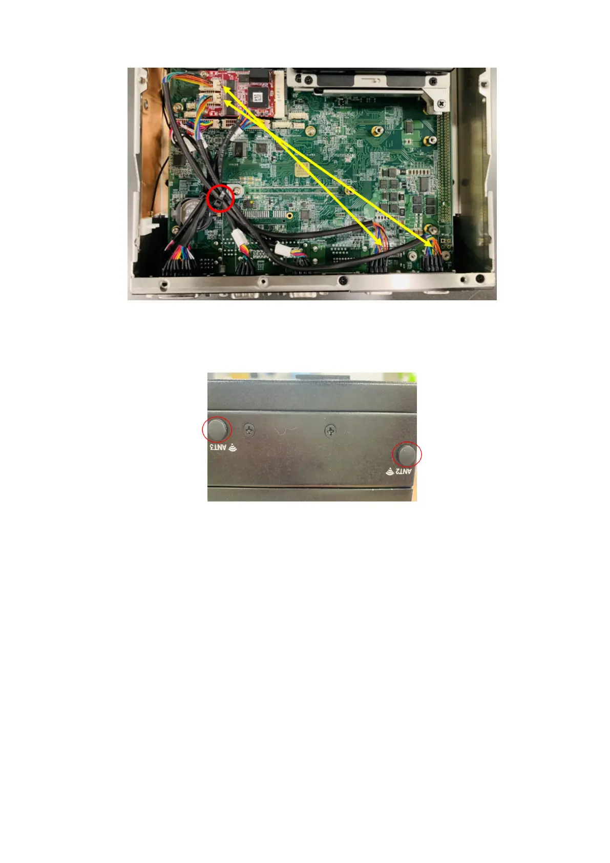
Figure 69. Cables from ports to Isolated COM 232 mPCIe module with cable tie (COM A > CN1, COM B > CN2)
13. Use the screws to reattach the bottom panel. See the screw locations in step 1.
14. Insert the rubber caps into the antenna holes, as shown in the following figure.
Figure 70. Antenna hole caps
44
Installation procedure for 2x isolated COM 422/485 or 232 uFM module