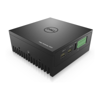
Figure 106. Cables from uFM to mPCIe module with cable ties
15. Use the screws to reattach the bottom panel. See the screw locations in step 1.
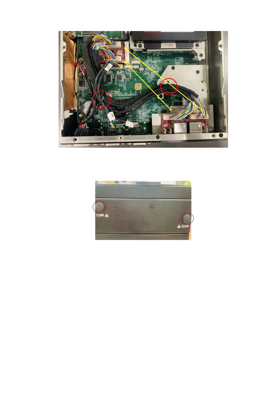
16. Insert the rubber caps into the antenna holes, as shown in the following figure.
Figure 107. Antenna hole caps
Installation procedure for 2x GbE LAN uFM module
63