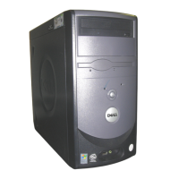
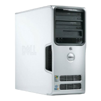
4-6 Dell Dimension V
xxx
and V
xxx
c Systems Service Manual
'ULYHV
The following subsections explain how to remove the front-panel inserts, the
drive cage, and the various types of drives in the drive bays. For additional
information about drive installation and configuration, see Chapter 3, “Install-
ing Drives,” in the
Reference and Troubleshooting Guide
.
5HPRYLQJDQG5HSODFLQJD)URQW3DQHO,QVHUW
Empty drive bays in the drive cage are covered by a front-panel insert. The
inserts for the 3.5-inch drives are mounted to the inside of the bezel. The insert
for the lower 5.25-inch bay is mounted to the drive cage, and instructions for
its removal are provided later in this chapter in the procedure for removing the
5.25-inch drives.
5 HPRYLQJD,QFK,QVH UW
After you have removed the computer cover, support beam, and the bezel,
remove the front-panel insert for the bay you plan to use. From the back of the
bezel, as shown for the mini tower chassis in Figure 4-4, press the release tab
to the side, rotate the insert toward you, and remove it from the bezel. For mini
tower computers, you must remove the upper insert to remove the lower
insert.
)LJXUH ,QFK ,QVHUW 5HPRYDO
release tab
tabs (2)

 Loading...

