Chapter 3- CIRCUIT THEORY
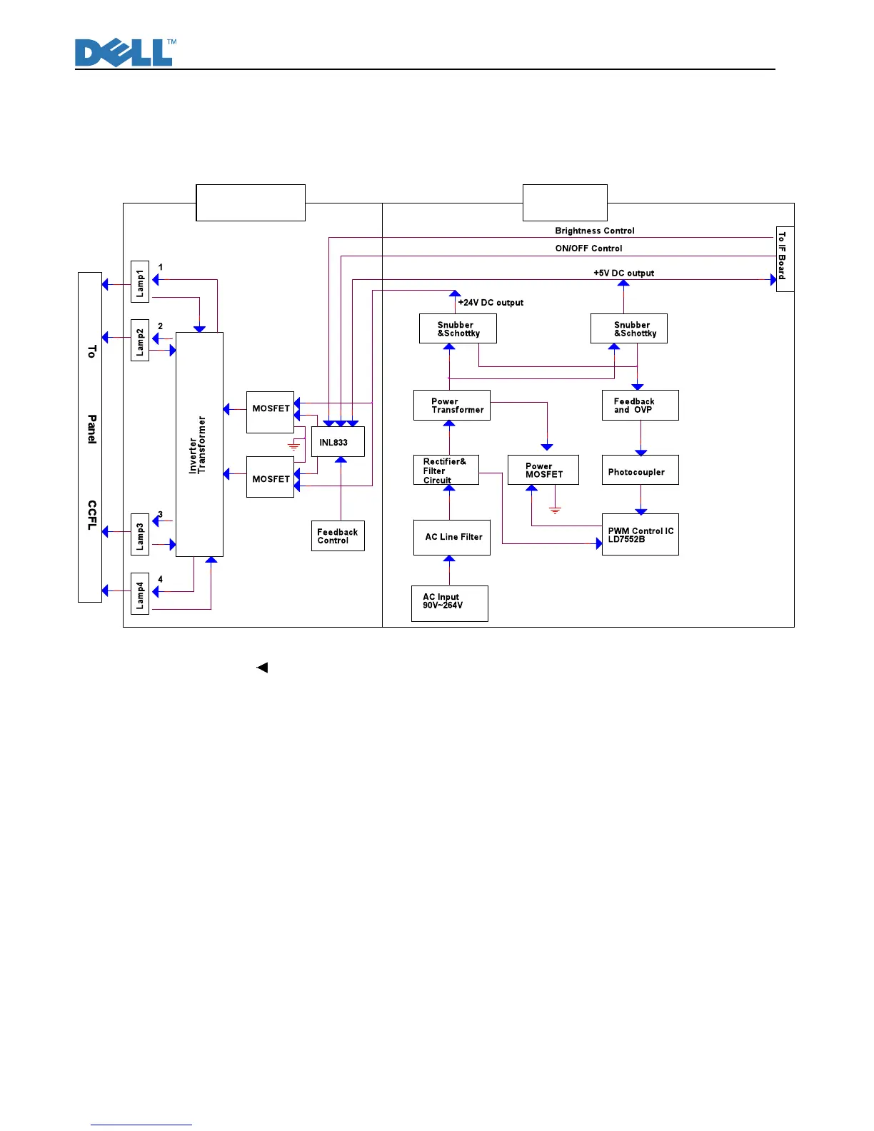
Block Diagram
There are 4pcs PCBA in this monitor, one is power& inverter board which is a single layer board, one is
interface board , one is keypad which is OSD control. The system function block diagram as below
This PWA is included switching power supplier, inverter for CCFL and interface board.(fig.1)
Fig.1