Table 7 Cabled PSU back panel features (continued)
Item Indicator, Button, or
Connector
Icon Description
5 PCIe expansion card
slots (2)
Enables you to connect two PCI Express
expansion cards.
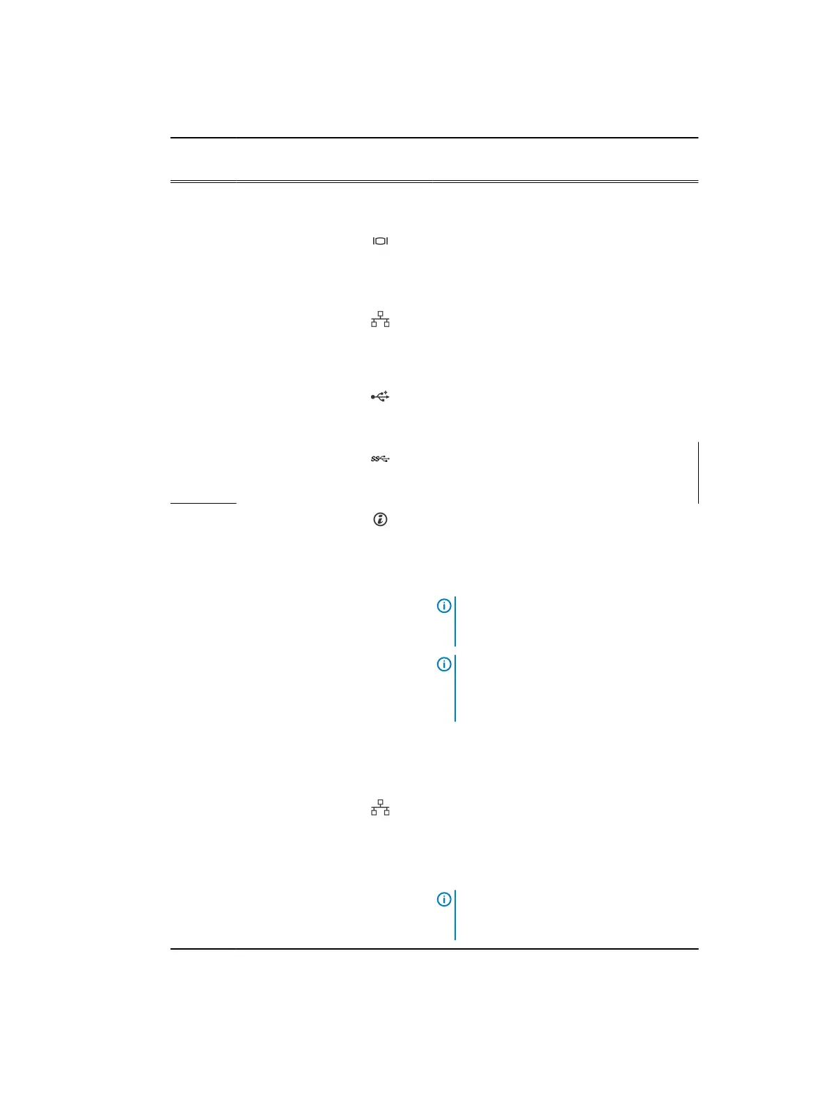
6 Video connector Use the video/VGA port to connect a display
to the system. For more information about the
supported video/VGA port, see the Technical
specifications section.
7 Ethernet port 2 Use the Ethernet port to connect Local Area
Networks (LANs) to the system. For more
information about the supported Ethernet
ports, see the Technical specifications section.
8 USB port Use the USB 2.0 port to connect USB devices
to the system. This port is 4-pin, USB 2.0
compliant.
9 USB port Use the USB 3.0 port to connect USB devices
to the system. These ports are 9-pin, USB 3.0
compliant.
10
System identification
button
Press the system ID button:
l
To locate a particular system within a
rack.
l
To turn the system ID on or off.
Note: To reset the iDRAC (if not disabled
in F2 iDRAC setup), press and hold the
button for more than 15 seconds.
Note: If the system stops responding
during POST, press and hold the system ID
button (for more than five seconds) to
enter the BIOS progress mode.
11 System identification
port
Use the system identification port to connect
the system status indicator assembly through
the optional cable management arm.
12 Ethernet port 3 Use the Ethernet port to connect Local Area
Networks (LANs) to the system. For more
information about the supported Ethernet
ports, see the Technical specifications section.
13 Ethernet port 4
14 Power supply unit
(PSU)
One 450 W cabled AC PSU.
Note: Cabled PSU is supported in systems
with cabled hard drives and the systems
with x4 backplane.
Dell PowerEdge R430 system overview
Dell PowerEdge R430 Owner's Manual 25

 Loading...


