Figure 21 Inside the system—with a cabled power supply (continued)
8. memory-module socket (A1, A5, A2, A6)
9. processor 1
10. memory-module socket (A3, A7, A4, A8)
11. cooling fan (5)
12. optical drive (optional)
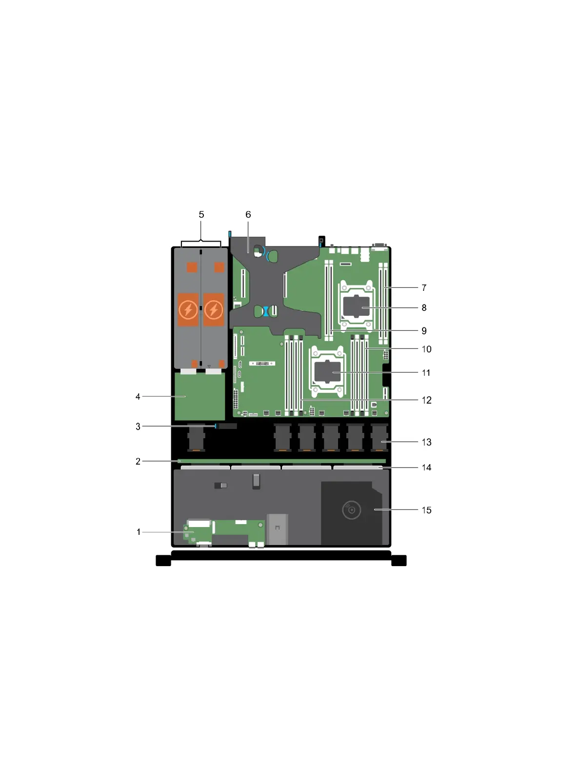
Figure 22 Inside the system—with redundant power supplies
1. control panel
2. hard drive/SSD backplane
3. cable routing latch
4. power interposer board
5. power supply units (2)
6. PCIe expansion card riser (optional)
Installing and removing system components
90 Dell PowerEdge R430 Owner's Manual

 Loading...


