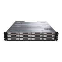
Dell EqualLogic PS-M4110 Installation Guide
For increased availability, the Ethernet ports on both PS-M4110 control modules are automatically connected
to each redundant M1000e IO module (IOM) of the configured fabric. (Assuming that both IO modules are
installed.) One port is active and one port is passive.
For example, if a PS-M4110 is configured for Fabric B, and both the B1 IOM and B2 IOM are installed, the
Ethernet ports from each control module are connected to both B1 and B2 IOMs. This provides a total of
four potential Ethernet paths. However, only one Ethernet path is active at any given time.
In the above example, if the B1 IO module fails, both active and passive PS-M4110 ports will automatically
failover to the B2 IO module.
See Figure 3 for an illustration of the above example, showing how the PS-M4110 control modules and
M1000e fabric IOMs are connected.
Figure 3: Example of Default Fabric B Network Paths
Active 10G path
Network path failover
Passive control module standby network paths
External stack or LAG connection
•
Stack Switches Together
When using a PS-M4110 inside an M1000e enclosure, the IO modules must be interconnected (stacked or
LAGged together).
For example, if fabric B is configured, the B1 and B2 IOMs must be stacked or LAGged together. The redun-
dant fabric IO modules must be connected using inter-switch links (stack interfaces or link aggregation
groups (LAG)). The links must have sufficient bandwidth to handle the iSCSI traffic.
 Loading...

