Installing the Hardware 5
NOTE: Coat the one-hole lug with an anti-oxidant compound prior to crimping.
Bring any un-plated mating surfaces to a shiny finish, and coat with an anti-oxidant
prior to mating. Plated mating surfaces must be clean and free from contamination.
Install the SFP+ QSFP+ Optics
The S4810 has 48 SFP+ optical ports and 4 QSFP+ optical ports. For supported
optics, refer to http://www.force10networks.com/products/specifications.asp.
CAUTION: Electrostatic discharge (ESD) damage can occur if components
are mishandled. Always wear an ESD-preventive wrist or heel ground strap
when handling the S4810 and its components.
WARNING: Follow all warning labels when working with optical fibers.
Always wear eye protection when working with optical fibers. Never look
directly into the end of a terminated or unterminated fiber or connector as it
may cause eye damage.
Step Task
1 Take the (1) M4x0.7 screw from the package.
2 Cut cable to desired length. Cable length must facilitate the proper
operation of fault interrupt circuits. Dell Force10 recommends using the
shortest cable route allowable.
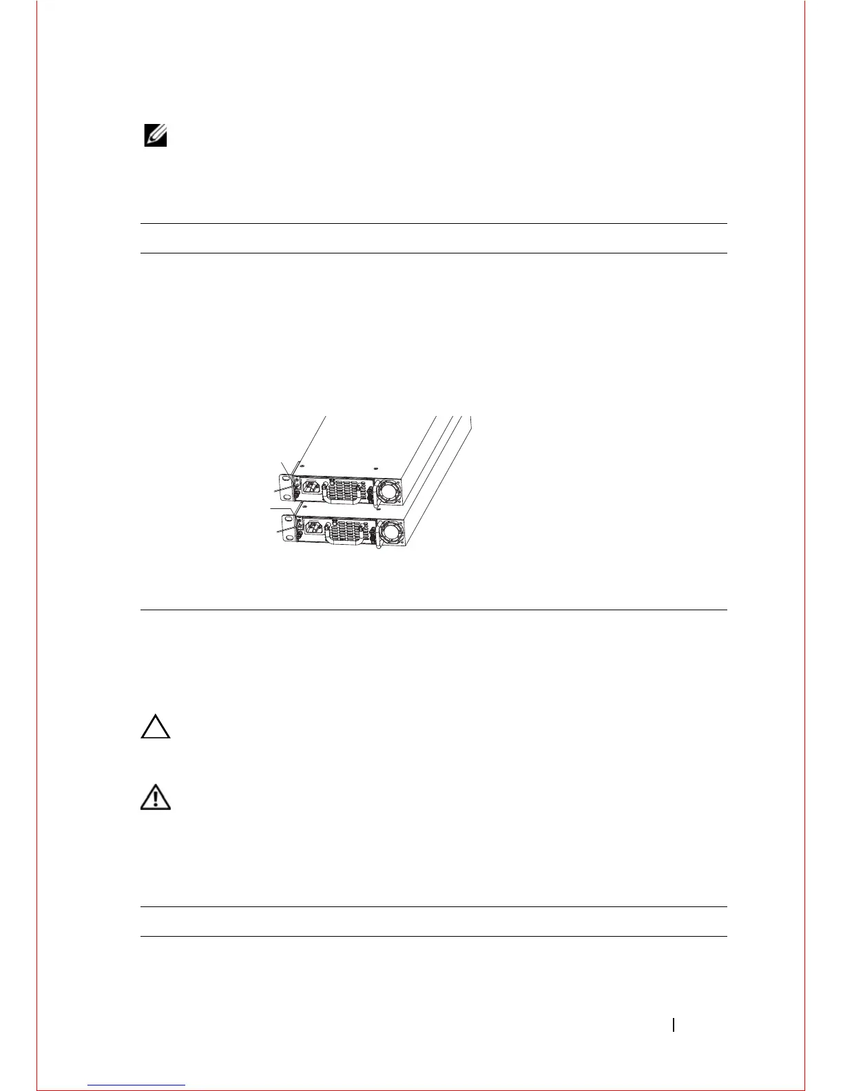
3 Attach the one-hole lug to the chassis as shown, using the supplied
screw with captive internal tooth lock washer. The screw should be
torqued to 20 in-lbs.
4 Attach the other end of the ground cable to a suitable ground point. The
rack installation ears are not a suitable grounding point.
Step Task
1 Position the optic so it is in the correct position. (The optic has a key that
prevents it from being inserted incorrectly.

 Loading...