7. System Fan Connector (FAN_SYS)
8. Intrusion Switch Connector (INTRUDER)
9. Processor Socket
10. CPU Power Connector (ATX_CPU)
11. CPU Fan Connector (FAN_CPU)
12. Memory Connector (DIMM1~ DIMM2)
13. Card Reader Connector (Card Reader)
14. Power Switch Connector (PWR_SW)
15. M.2 SSD connector
16. SATA 0 Connector (Blue color)
17. SATA 2 Connector (White color)
18. Internal Speaker Connector (INT_SPKR)
19. SATA 3 Connector (Black color)
20. ATX Power Connector (ATX_SYS)
21. HDD_ODD_Power Cable Connector (SATA PWR)
22. M.2 WLAN connector
23. Coin cell battery
24. CMOS_CLR/Password/Service_Mode Jumper (JMP1)
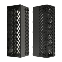
Side cover
Removing side cover
1. Follow the procedure in Before working inside your computer.
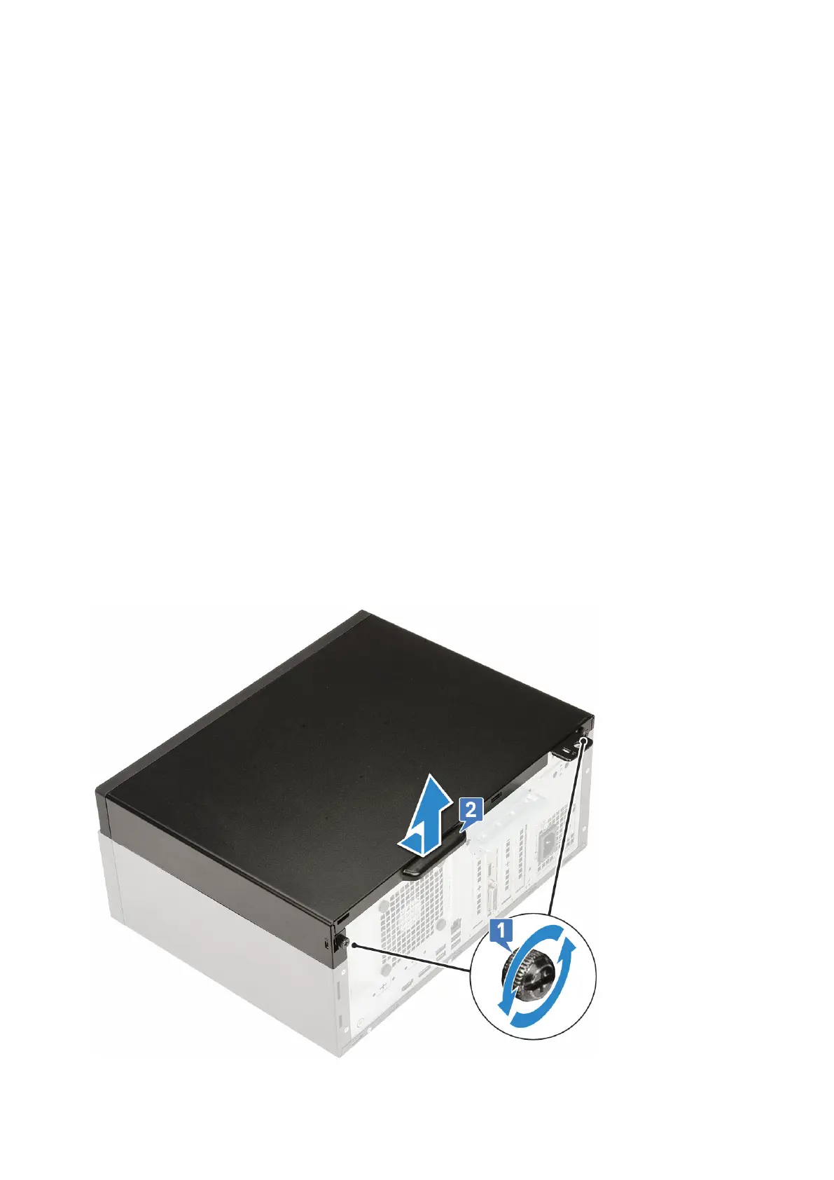
2. To remove the cover:
a. Loosen the captive screws that secure the cover to the computer [1].
b. Slide the cover towards the back of the system and lift it from the system [2].
Removing and installing components
15