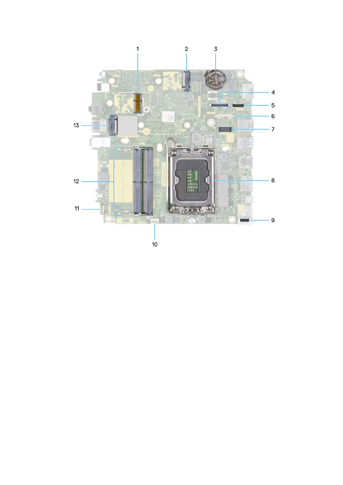
Figure 47. Image: System board connectors
1. M.2 WLAN connector
2. M.2 SSD PCIe connector (M.2 2230 or M.2 2280) (M.2 PCIe SSD-1)
3. Coin-cell battery
4. Optional video connector (VGA Port/DisplayPort 1.4a (HBR3)/HDMI 2.1 Port/Type-C DisplayPort) (VIDEO)
5. Type-C signal connector (SIGNAL)
6. Type-C USB connector (TYPE-C)
7. Optional PS/2, serial port connector (KB MS SERIAL)
8. Processor socket (CPU)
9. Type-C power connector (TOPPOWER)
10. Fan connector (FAN CPU)
11. Internal speaker connector (INT SPKR)
12. Memory-module slots (DIMM1 and DIMM2)
13. M.2 SSD PCIe connector (M.2 2230 or M.2 2280) (M.2 PCIe SSD-0)
The following image(s) indicate the location of the system board and provides a visual representation of the installation
procedure.
72
Removing and installing Field Replaceable Units (FRUs)