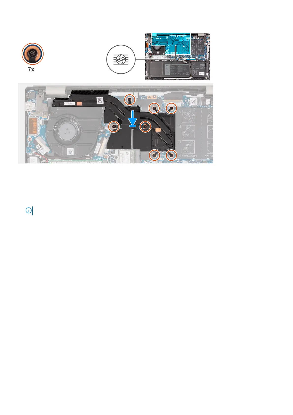
Steps
1. Place the heat-sink on the system board.
2. Align the screw holes on the heat sink to the screw holes on the system board.
3. In sequential order (1 > 2 > 3 > 4 > 5 > 6 > 7) tighten the seven captive screws that secure the heat sink to the system
board.
NOTE: The number of screws varies depending on the configuration ordered.
Next steps
1. Install the base cover.
2. Exit Service Mode.
3. Follow the procedure in After working inside your computer.
Power button with optional fingerprint reader
Removing the power button with optional fingerprint reader
Prerequisites
1. Follow the procedure in Before working inside your computer.
2. Enter Service Mode.
3. Remove the base cover.
4. Remove the I/O board.
About this task
The following image(s) indicate the location of the power button with optional fingerprint reader and provides a visual
representation of the removal procedure.
50
Removing and installing components