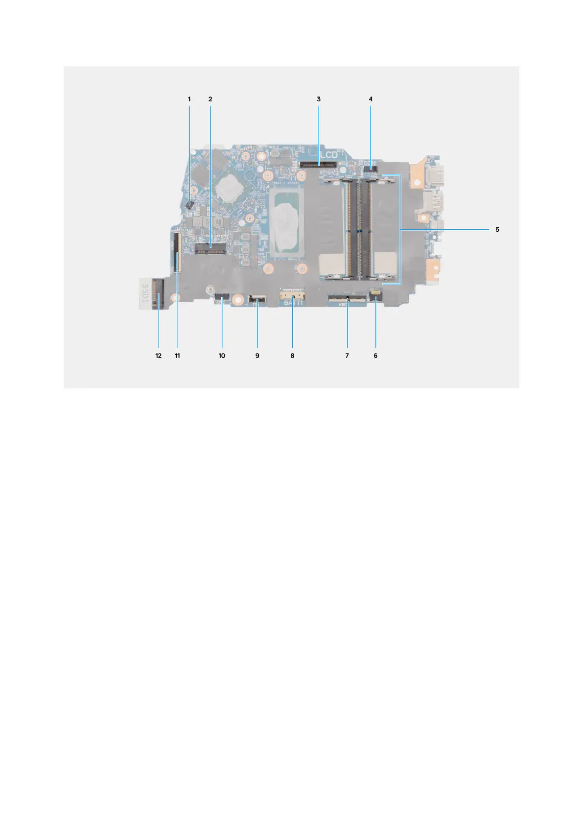
Figure 97. Connectors on the system board
1. Fan-cable connector (FN1)
2. M.2 wireless-card connector
3. Display-cable connector (LCD)
4. Power port connector (DC IN1)
5. Memory module connector
6. Keyboard-backlight cable connector (KBBL1)
7. Keyboard-cable connector (KB1)
8. Battery-cable connector (BATT1)
9. Touchpad-cable connector (TP1)
10. Speaker-cable connector (SPK1)
11. I/O-board cable connector (IOBD1)
12. M.2 solid-state drive connector (SSD1)
The following images indicate the location of the system board and provide a visual representation of the removal procedure.
128
Removing and installing Field Replaceable Units (FRUs)
 Loading...