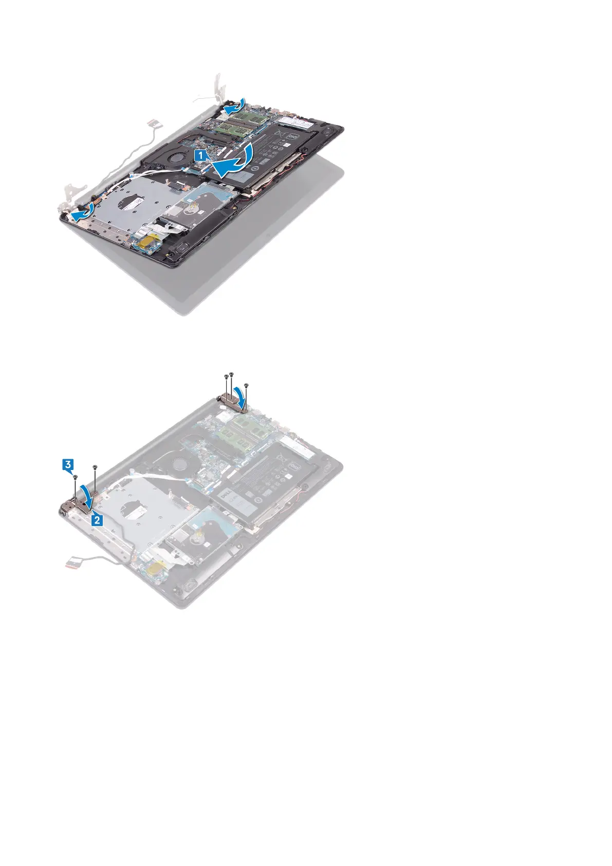
2. Using the alignment posts, press the hinges down on the system board and the palm rest and keyboard assembly.
3. Replace the five screws (M2.5x5) that secure the left and right hinges to the system board and palm rest and keyboard
assembly.
4. Route the display cable through the routing guides on the fan and the palm rest and keyboard assembly.
5. Slide the display cable to the connector on the system board and close the latch to secure the cable.
6. Press down on the latch to connect the optical-drive connector board cable to the optical-drive connector board.
7. Press down on the latch to connect the optical-drive connector board cable to the system board.
62
Replacing the power-adapter port