Removing the display assembly
NOTE: Before working inside your computer, read the safety information that shipped with your computer and follow the
steps in Before working inside your computer. After working inside your computer, follow the instructions in After working
inside your computer. For more safety best practices, see the Regulatory Compliance home page at www.dell.com/
regulatory_compliance.
Prerequisites
1. Remove the optical drive.
2. Remove the base cover.
3. Remove the wireless card.
Procedure
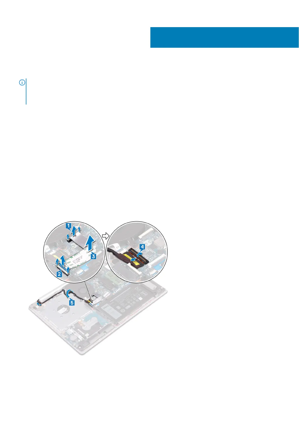
1. Lift the latch and disconnect the optical-drive connector-board cable from the system board.
2. Lift the latch and disconnect the optical-drive connector-board cable from the optical-drive board connector.
3. Lift the optical-drive connector-board cable off the system board.
4. Open the latch and disconnect the display cable from the system board.
5. Note the routing of the display cable and remove the cable from its routing guides on the fan and palm rest and keyboard
assembly.
6. Remove the five screws (M2.5x5) that secure the left and right hinges to the system board and palm rest and keyboard
assembly.
7. Open the hinges.
34
64 Removing the display assembly