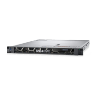
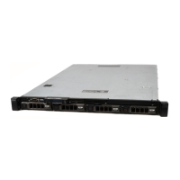
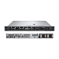
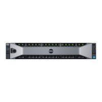
Figure 22. Inside the system—with redundant power supplies
1. control panel 2. hard drive/SSD backplane
3. cable routing latch 4. power interposer board
5. power supply units (2) 6. PCIe expansion card riser (optional)
7. memory-module socket (B3, B4) 8. processor 2
9. memory-module socket (B1, B2) 10. memory-module socket (A1, A5, A2, A6)
11. processor 1 12. memory-module socket (A3, A7, A4, A8)
13. cooling fan (6) 14. hard drives/SSDs
15. optical drive
83
 Loading...


