Table 20. Connector descriptions for 8 x 2.5-inch drive NVMe backplane with fPERC, Butterfly riser,
BOSS riser, SNAPI
From To
BP_PWR_1 (backplane power connector) SIG_PWR_1 (system board power connector)
SYS_PWR2 (system board power connector) CPU_PWR2 (PSU power connector)
DST_PA1 and DST_PB1 (backplane SATA connector, cable
marking BP PA1 and PB1)
CTRL_SRC_PB1 (fPERC connector on the backplane)
DST_PA2 and DST_PB2 (backplane SATA connector, cable
marking BP PA2 and PB2)
CTRL_SRC_PB1 (fPERC connector on the backplane)
CTRL_DST_PA1 (fPERC connector on the backplane) SL3_CPU1_PB2 (signal connector on the system board, cable
marking MB SL3)
Connect riser SL8_CPU1_PB4 (signal connector on the system board, cable
marking MB SL8)
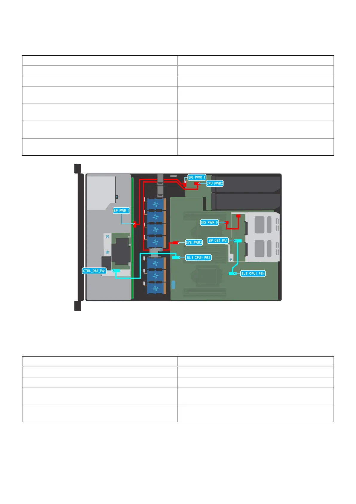
Figure 43. Cable routing - 4 x 3.5-inch drive SAS/SATA backplane wih fPERC with rear drive cage with NVMe
backplane
Table 21. Connector descriptions for 4 x 3.5-inch drive SAS/SATA backplane wih fPERC with rear drive
cage with NVMe backplane
From To
BP_PWR_1 (backplane power connector) SIG_PWR_1 (system board power connector)
SYS_PWR2 (system board power connector) CPU_PWR2 (PSU power connector)
CTRL_DST_PA1 (fPERC connector on the backplane) SL3_CPU1_PB2 (signal connector on the system board, cable
marking MB SL3)
BP_DST_PA1 (backplane SATA connector, cable marking BP
PA1)
SL8_CPU1_PB4 (signal connector on the system board, cable
marking MB SL8)
54 Installing and removing system components
 Loading...