4. Install the:
a) Hard drive and optical drive module
b) Front bezel
c) Side cover
5. Follow the procedure in After working inside your computer.
Intel Optane card
Removing the Intel Optane card
1. Follow the procedure in Before working inside your computer.
2. Remove the:
a) Side cover
b) Front bezel
c) Hard drive and optical drive module
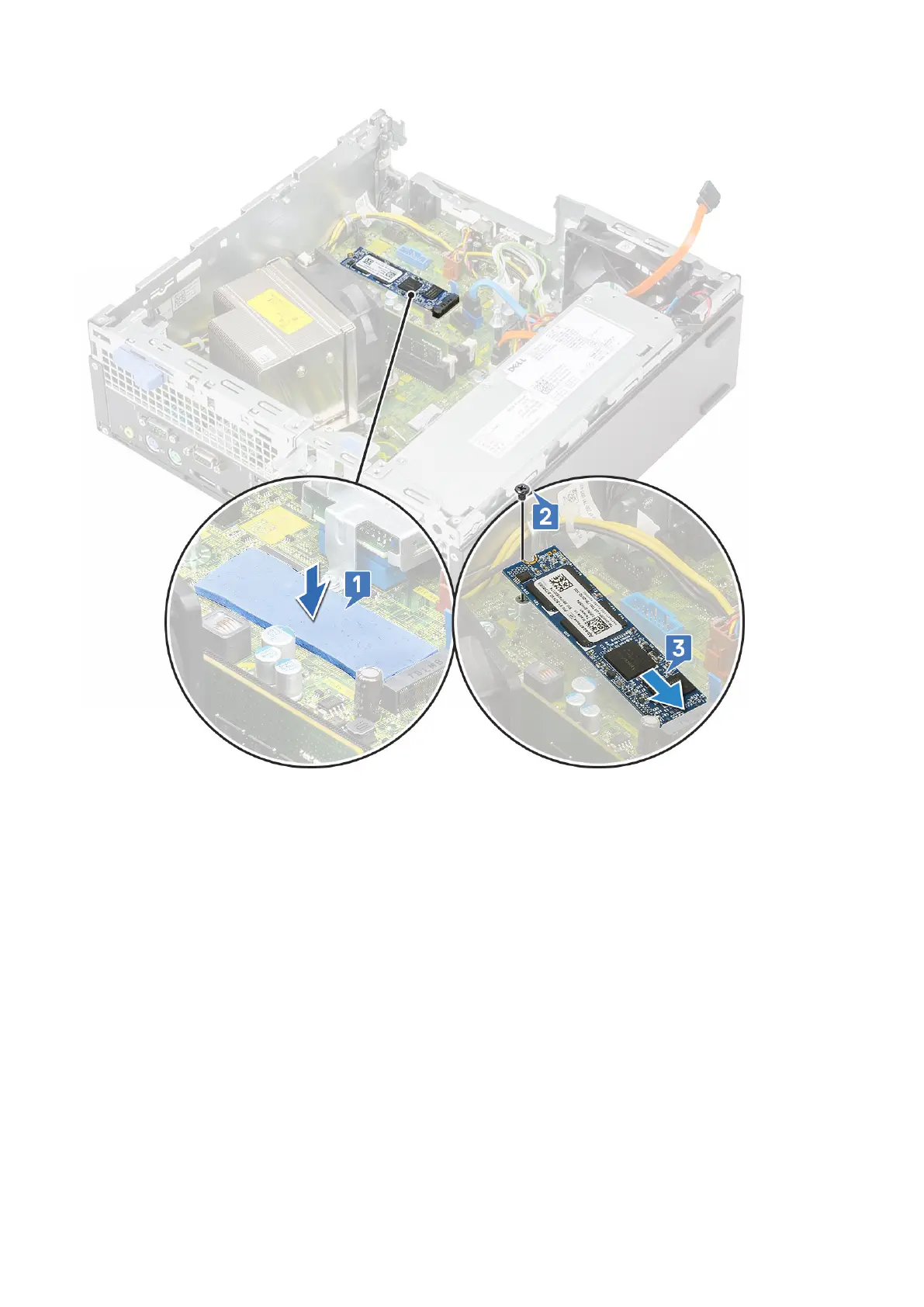
3. To remove the Intel Optane card:
a) Remove the single (M2 x 3.5) screw that secures the Intel Optane card to the system board [1].
b) Lift and pull out the Intel Optane card from its connector on the system board [2].
c) Peel the thermal pad [3].
Removing and Installing components
53