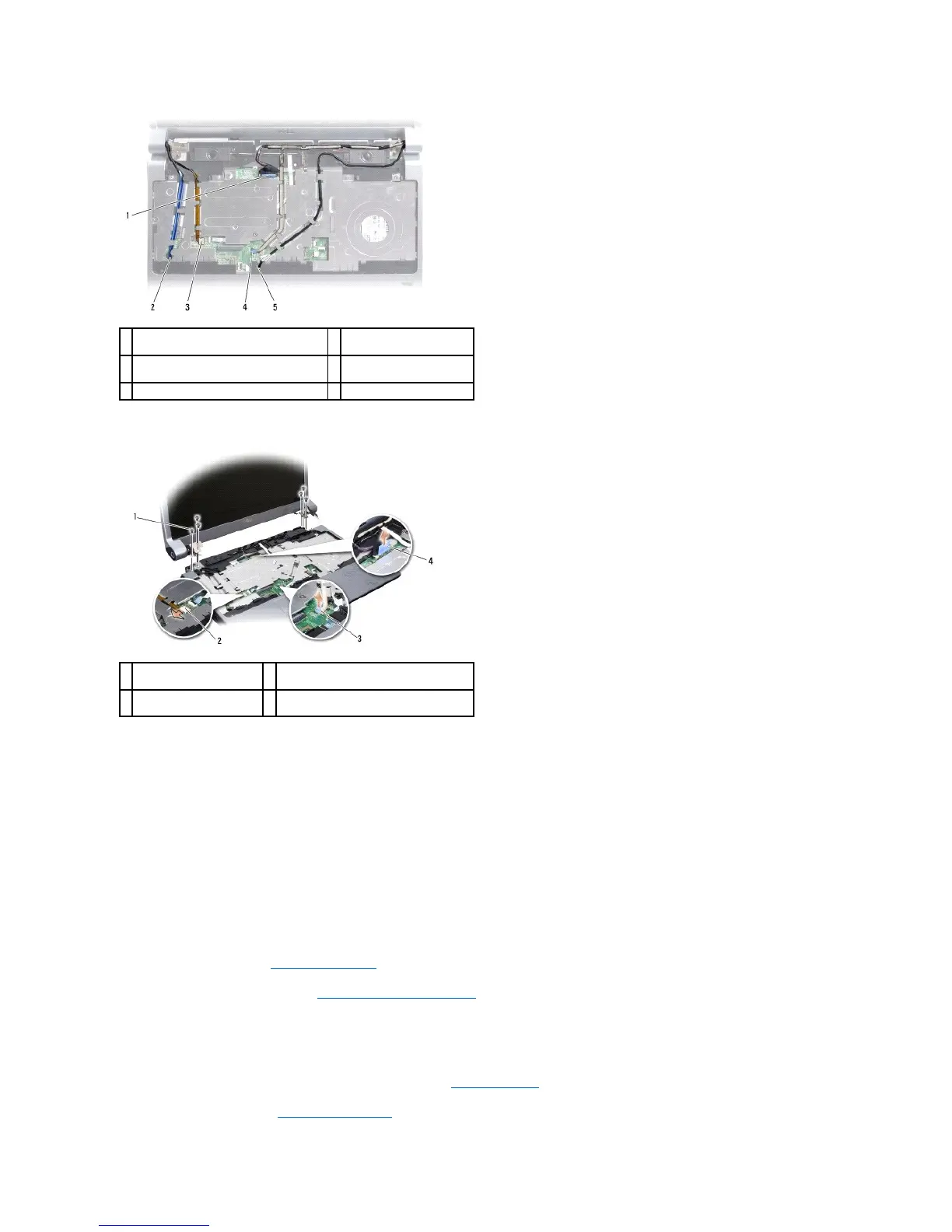
11. Make note of the cable routing and carefully dislodge the cables from their routing guides.
12. Remove the three screws from each side of the display assembly.
13. Remove the display assembly.
Replacing the Display Assembly
1. Place the display assembly in position and replace the three screws on each side.
2. Route the optional camera cable, Wi-Fi Sniffer/Power Button Board cable, and display cable through the routing guides and connect the cable connectors
to the system board.
3. Make note of the cable routing and carefully slide the Mini-Card antenna cables through the system board and into their routing guides.
4. Replace the keyboard (see Replacing the Keyboard).
5. Replace the center control cover (see Replacing the Center Control Cover).
6. Turn the computer over.
7. Make note of the cable routing and carefully insert the Mini-Card antenna cables through their routing guides.
8. Reconnect the Mini-Card cables to the Mini-Cards, if applicable (see Wireless Mini-Cards).
9. Replace the base cover (see Replacing the Base Cover).