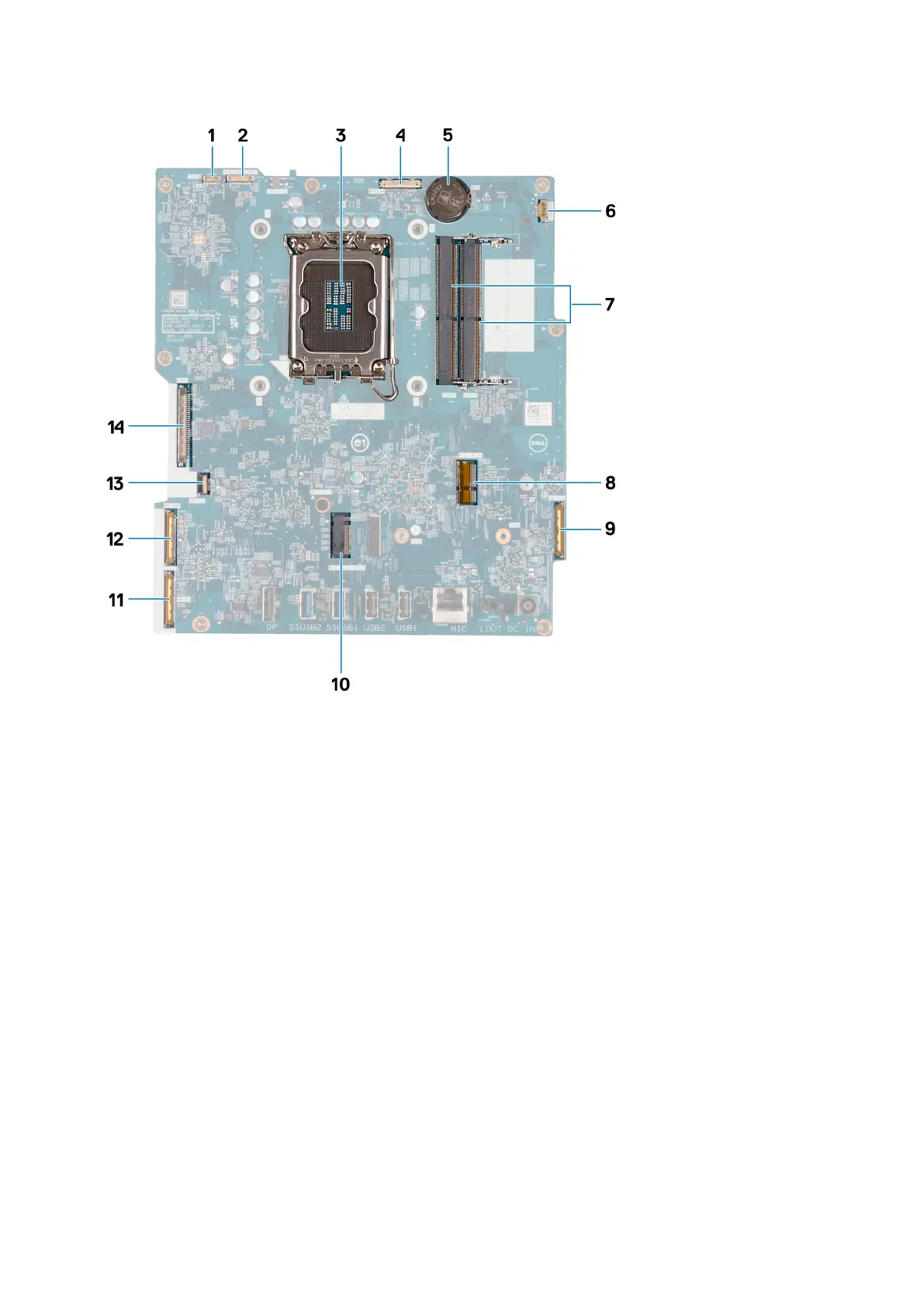
1. Touchscreen cable (TOUCH)
2. Display-backlight cable (LCD BACKLIGHT)
3. Processor socket (CPU)
4. Camera cable (WEBCAM)
5. Coin-cell battery socket (RTC)
6. Fan cable (FAN CPU)
7. Memory slots x2 (DIMM1 + DIMM2)
8. Wireless-card slot (M.2 WLAN)
9. Audio cable (MB-AUDIO)
10. Solid-state drive slot (M.2 PCIe SSD 0)
11. high-speed cable (MB-HS)
12. power cable (MB-PWR)
13. hard-drive cable (SATA 1)
14. display cable (CVDS)
The following image(s) indicate the location of the system board and provides a visual representation of the removal procedure.
Removal and installation procedures for Energy Efficient processors
141