Chapter 4 Parameters|
4-38 Revision May 2008, ME14, SW V3.04
Settings Function Description
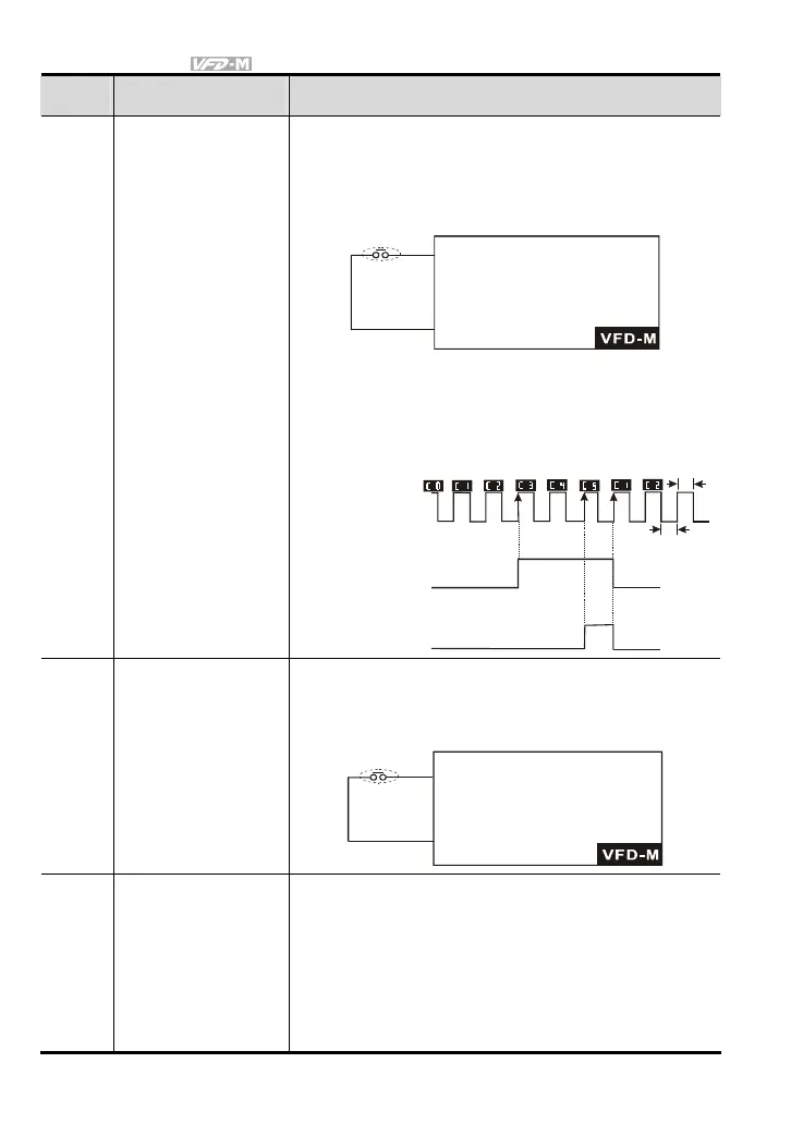
18 Counter Trigger Signal
Parameter value 18 programs Multi-Function Input Terminal:
M1 (Pr.38), M2 (Pr.39), M3 (Pr.40), M4 (Pr.41) or M5 (Pr.42)
to increase the AC drive
’
s internal counter. When an input is
received, the counter is increased by 1.
GND
18 counter
trigger signal
input.
Mx counter value increase by
1 when closed.
Trigger
Note: The Counter Trigger input can be connected to an
external Pulse Signal Generator when counting a
process step or unit of material. See the diagram
below.
2ms
2ms
Indication value
(Pr.64=1)
Counter trigger signal
Multi-function input terminal
Signal output with Pr.97
counter value is attained.
(Pr.97=3)
(Pr.45/46=13)
Signal output with Pr.96
counter value is attained.
(Pr.96=5)
(Pr.45/46=14)
The trigger timing
can't be less than
2ms.(<250Hz)
(Pr.38 to Pr.42 =18)
19 Counter Reset
Parameter value 19 programs Multi-Function Input Terminal:
M1 (Pr.38), M2 (Pr.39), M3 (Pr.40), M4 (Pr.41) or M5 (Pr.42)
to reset the counter.
GND
19 reset the
counter value.
Mx "close": reset counter.
Reset counter
20 No Function
Enter value (20) to disable any Multi-Function Input Terminal:
M1 (Pr.38), M2 (Pr.39), M3 (Pr.40), M4 (Pr.41) or M5 (Pr.42)
Note: Purpose of this function is to isolate unused Multi-
Function Input Terminals. Any unused terminals should
be programmed to 20 to insure they have no effect on
drive operation.