6
FASTENING PLANER TO SUPPORTING SURFACE
ASSEMBLING CUTTERHEAD
RAISING AND LOWERING
HANDLE
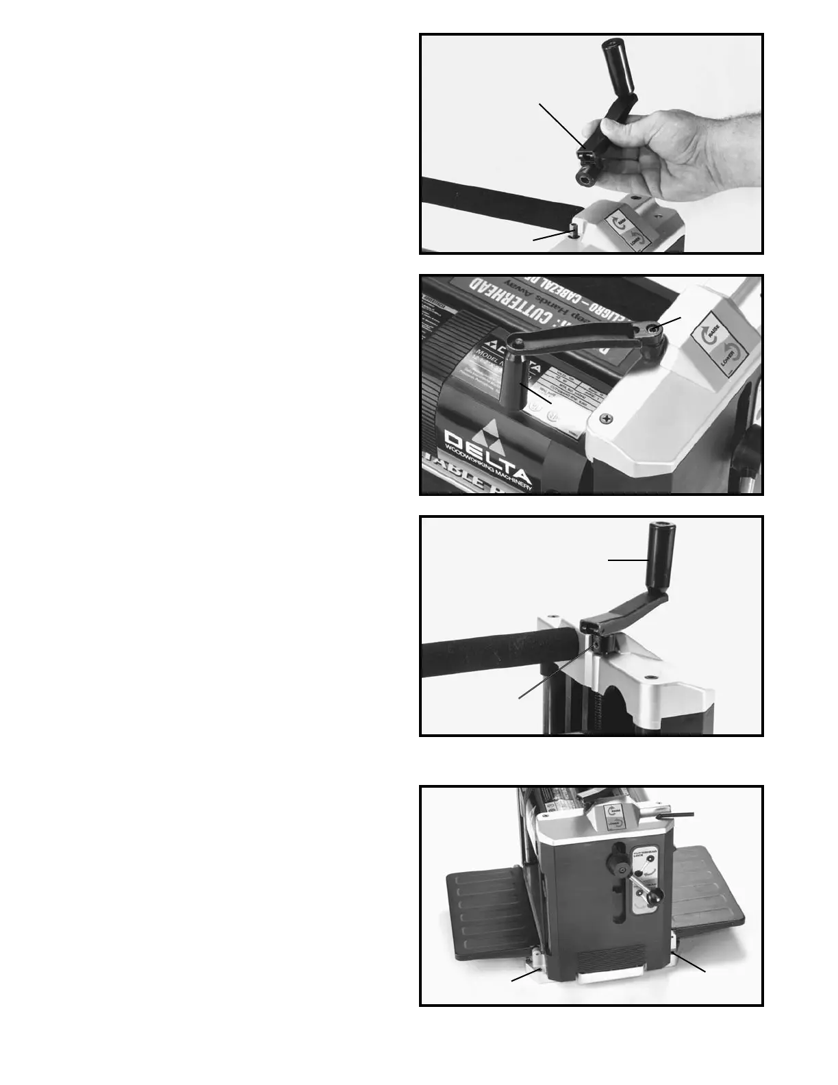
1. Assemble the cutterhead raising and lowering handle
(A) Fig. 7, to shaft (B), making certain flat on shaft is
engaged with flat in handle.
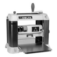
2. Fasten cutterhead raising and lowering handle (A)
Fig. 8, to shaft using the M5 x 20mm hex socket head
screw (C) with wrench supplied.
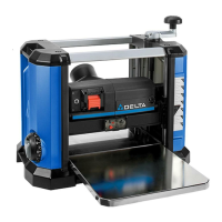
3. Rotate handle (A) to the operating position as shown
in Fig. 9, and tighten set screw (D).
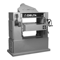
If during operation there is any tendency for the planer
to tip over, slide, or walk on the supporting surface, the
planer must be secured to the supporting surface using
the four holes in the base of the machine, two of which
are shown at (A) Fig. 10. Only operate planer on a flat
level surface.
If assembled to the stand, place the planer on the stand
and align the four holes in the base of the machine, two
of which are shown at (A) Fig. 10, with the four holes in
the top of the stand. Place the hex head flange bolt
through the holes in the planer and the stand, and thread
the flange nut onto the hex head flange bolt and tighten
securely. Only operate planer, attached to stand, on a
flat level surface.
Fig. 7
Fig. 8
Fig. 9
Fig. 10
A
B
C
A
A
D
A
A