Do you have a question about the Delta 22-580 and is the answer not in the manual?
Explains the importance and procedure for grounding the machine to prevent electric shock.
Covers raising/lowering the head assembly and locking the cutterhead to prevent snipe.
Describes how to set the depth stop for repetitive planing depths from 1/8" to 6-1/2".
Explains how to use the indicator for precise measurement of cuts and its proper engagement.
Details the process for checking and adjusting table extensions to be level with the planer table.
Provides steps for adjusting the outfeed roller height using a gauge block and feeler gauge.
Detailed instructions for safely removing, reversing, or installing the planer knives.
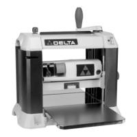
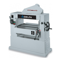
The Delta Model 22-580 is a 13" Two-Speed Finishing Planer designed for woodworking tasks, specifically for planing wood to a desired thickness and achieving a smooth finish. This portable planer is equipped with a powerful 15 amp, 120-volt motor and a two-knife cutterhead, making it suitable for both dimensioning and finishing operations.
The primary function of the planer is to reduce the thickness of wood stock and create smooth, flat surfaces. It achieves this by feeding a workpiece through a rotating cutterhead equipped with sharp knives, which shave off thin layers of wood. The depth of cut is adjustable, allowing for precise control over the final thickness of the workpiece. The machine also features a dual-speed control, offering different cuts per inch for either rapid material removal (dimensioning) or a finer finish.
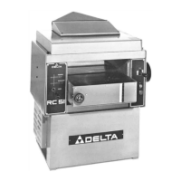
The planer's head assembly, which contains the cutterhead, feed rollers, chip deflector, and motor, can be raised or lowered to control the depth of cut. One full revolution of the cutterhead adjusting handle moves the cutterhead up or down 1/16". A cutterhead lock is incorporated to help eliminate "snipe" – a slight depression at the ends of a planed board – by securing the cutterhead during operation.
For accurate thickness measurement, the planer is equipped with a dual English/Metric scale and a pointer. This allows the user to monitor the thickness of the finished workpiece. The pointer can be adjusted for calibration by loosening a screw, planing a piece of wood, measuring its thickness, and then realigning the pointer.
A unique feature is the adjustable indexing ring on the cutterhead adjusting handle, which facilitates fine adjustments. Each indicator on this ring is equivalent to 1/128" of movement, enabling minute cuts for highly precise work. Additionally, a blade zero indicator helps mark the exact point where the cutterhead and workpiece make contact, allowing for precise cut measurements. This indicator is engaged by pushing it down and disengages once contact is made with the workpiece.
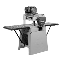
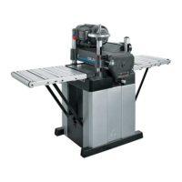
The planer includes infeed and outfeed table extensions to support longer workpieces. These tables are shipped in an "UP" position and must be lowered for operation. They can also be leveled with the main planer table to ensure consistent planing results and prevent snipe. An optional 4" reversible dust collection attachment can be mounted on either side of the machine to connect to a dust collection system, helping to maintain a clean work environment.
For safety and convenience, the planer has a stock transfer bar, which is particularly useful for transferring long workpieces from the outfeed end back to the infeed end for additional cuts. This minimizes the need to carry heavy or long boards around the machine.
Operating the planer involves several key steps and considerations to achieve optimal results and ensure safety. Before starting, the machine should be properly assembled, including attaching the cutterhead lock handle and the cutterhead adjustment handle. The table extensions must be lowered and, if necessary, leveled with the planer table.
The planer must be secured to a supporting surface to prevent tipping, sliding, or "walking" during operation. Four holes are provided in the base for this purpose. It is crucial to operate the planer on a flat, level surface.
The on/off switch is located on the front of the planer motor. To turn the machine "ON," the switch is moved up, and to turn it "OFF," the switch shield is pushed down. For safety, when the machine is not in use, the switch should be locked in the "OFF" position to prevent unauthorized use. This is done by raising the infeed table to an upright position and placing a padlock through a designated hole in the planer and the infeed table.
When planing, it is recommended to true up one face of the board using a jointer first, then plane the surfaced side face down until the opposite side is flat. Thin cuts should be made with each pass, alternating sides if necessary, to prevent twisting, warping, or bowing. Long workpieces should always be supported at both ends. For best results, the cutterhead lock should be engaged before planing, and planing should always be done with the grain. The planer table should be kept clean and occasionally waxed to reduce friction.
The two-speed control allows the user to select between "Dimensioning" speed (60 cuts per inch) for sizing boards and "Finishing" speed (90 cuts per inch) for a smoother final surface. It is important to change speeds only while the motor is running and not while planing. The speed control must be fully engaged before feeding work material.
The recommended depth of cut varies depending on the wood type and width. For soft woods up to 6" wide, an 1/8" depth of cut is possible, while for hard woods up to 4" wide, an 1/8" depth of cut is also recommended. For wider soft woods (10", 12", and 13"), a maximum depth-of-cut of 1/16" is recommended. For wider hard woods (10", 12", and 13"), a maximum depth-of-cut of 3/64" is recommended. Continuous operation at more than 3/64" can cause motor damage. A shallow depth-of-cut generally produces a better finish.
To ensure even wear of the knives, it is advisable to feed wood through different spots on the table whenever possible.
Regular maintenance is essential for the planer's longevity and optimal performance. This includes replacing knives, inspecting and replacing brushes, lubrication, and general cleaning.
The planer's knives are double-edged and reversible. When one edge becomes dull or chipped, the knives can be turned end-for-end. To change knives, the two top covers must be removed, the head assembly raised to 4", and the cutterhead guard removed. The cutterhead is then rotated until the lock engages, and the seven screws securing the locking bar are loosened. A magnetized knife transfer tool is provided to safely remove and install knives, ensuring proper alignment with the pins in the cutterhead and locking bar. After replacing knives, the screws are tightened, the cutterhead lock is depressed, and the cutterhead guard and top covers are reinstalled. Care must be taken as the knives are very sharp.
Brush inspection and replacement are also critical. Brush life varies depending on motor load. Brushes should be checked after the first 50 hours of use for a new machine or new set of brushes, and then every 10 hours thereafter until replacement is necessary. Brushes are located in the motor housing. Both brushes should be replaced if the carbon is worn to 3/16" in length, or if the spring or shunt wire is burned or damaged.
Lubrication is required periodically for the gears in the gearbox, the feed roller bushings, and the spindles and columns. This involves removing the top covers, depth stop assembly, and gear housing cover to apply extreme pressure lithium grease to the gear teeth. The columns and spindles should be cleaned and oiled with lightweight machine oil. The feed roller bushings also require oil, applied to each end of the feed rollers. Additionally, the bearing blocks should be lubricated by placing 2 drops of 30 weight oil on the shaft at the bearing block, allowing it to flow in.
General cleaning involves periodically blowing out all air passages with dry compressed air. Plastic parts should be cleaned with a soft damp cloth, avoiding solvents that could damage the material. The infeed and outfeed rollers should be cleaned periodically with soap, water, and a scotch-brite pad.
To protect the cast iron tables from rust, they should be cleaned and protected weekly. This process involves using WD-40® and a Scotch-Brite™ Blending Hand Pad with a pushblock to polish the table surface, followed by degreasing and applying TopCote® Aerosol.
In case of a failure to start, the user should check the cord plug for good contact with the outlet and inspect for blown fuses or open circuit breakers in the line.
| Type | Benchtop Planer |
|---|---|
| Motor | 15 Amp |
| Cutting Width | 13 inches |
| Maximum Cutting Depth | 1/8 inch |
| Cutterhead Speed | 10, 000 RPM |
| Feed Rate | 26 feet per minute |
| Number of Knives | 2 |
| Dust Port Size | 2.5 inches |