EasyManua.ls Logo

Delta RC-33 - User Manual

Delta RC-33
18 pages
Print Icon
To Next Page IconTo Next Page
Loading...
Model
RC-33
13"
Planer
Dated
12-1-84
Part
No.
428-06-651-0003
Delta
International
Uacttmery
Corporation.
Inc
INSTRUCTION
MANUAL
Question and Answer IconNeed help?

Do you have a question about the Delta RC-33 and is the answer not in the manual?

Summary

Safety Rules for All Tools

Personal Protection and Preparedness

Emphasizes wearing safety glasses, proper apparel, and avoiding distractions like drugs or alcohol.

Safe Operation and Environment

Details on keeping guards in place, clean workspace, avoiding overreaching, and proper tool use.

Electrical and Machine Safety

Guidelines on grounding, removing wrenches, avoiding accidental starts, and checking damaged parts.

Unpacking the Planer

Planer Cleaning Procedures

Assembling Lifting Handles

Assembling Optional 50-315 Stand

Mounting Planer to Stand or Bench

Assembling Head Adjustment Handle

Switch Assembly for Three Phase Machine

Single Phase Motor and Belt Assembly

Feed Roll Shifter Mechanism Assembly

Electrical Connection Guidelines

Single Phase Electrical Connections

Details on connecting the single phase planer to a grounded 3-conductor receptacle.

Three Phase Electrical Connections

Instructions for connecting the three phase planer to a power system, including wire interchangeability.

Voltage Conversion: 220 V to 440 V Three Phase

Operating Controls Overview

Planer Switch Locations

Identifies the ON-OFF switch location for single and three phase machines.

Overload Protection and Reset Procedures

Explains how the overload protection works and how to reset it for both single and three phase machines.

Adjusting the Depth of Cut

Anti-Kickback Finger Inspection

Feed Roll Speed Control and Engagement

Adjusting Belt Tension

Cutterhead Knife Maintenance

Feed Roll Spring Tension Adjustment

Outfeed Roll Height Adjustment

Chipbreaker Adjustment Procedure

Table Roll Height Adjustment

Cuttinghead Parallelism Adjustment

Overview

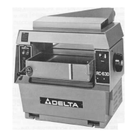
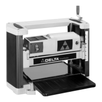
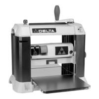
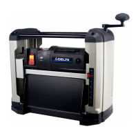
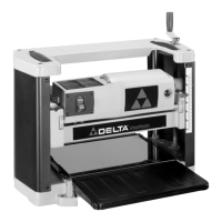
The device described in this manual is a Delta Model RC-33 13" Planer, designed for woodworking applications to smooth and reduce the thickness of lumber.

Function Description

The planer's primary function is to process rough lumber into boards of uniform thickness and smooth surfaces. It achieves this by feeding wood stock over a rotating cutterhead equipped with sharp knives, which shave off thin layers of material. The depth of cut is adjustable, allowing users to control the final thickness of the planed material. The machine is equipped with feed rolls that automatically advance the stock through the cutterhead. Anti-kickback fingers are integrated to prevent the workpiece from being ejected back towards the operator, enhancing safety. The machine can be configured for either single-phase or three-phase electrical operation, depending on the model purchased and the user's power supply.

Important Technical Specifications

  • Model: RC-33
  • Planer Size: 13" (referring to the maximum width of material it can plane)
  • Electrical Configuration:
    • Single Phase Machine: Wired for 230 Volts, supplied with a power cord featuring two flat, current-carrying prongs and one round or "U" shaped longer ground prong.
    • Three Phase Machine: Wired for 220 Volts, with an option to change to 440 Volts.
  • Motor Horsepower:
    • Three Phase Motor: 3 horsepower
    • Single Phase Motor: 2 horsepower
  • Maximum Depth of Cut (Full Width Planing):
    • With 3 HP Three Phase Motor: 3/16" (4.763 mm)
    • With 2 HP Single Phase Motor: 1/8" (3.175 mm) – a limiter is provided to restrict the depth of cut to 1/8" for single-phase machines.
  • Head Assembly: Raises and lowers on four precision ground steel columns.
  • Feed Rolls: Features a spiral, serrated infeed roll and a solid steel outfeed roll. The outfeed roll is factory-set to .040" below the cutting circle.
  • Table Rolls: Two table rolls aid in feeding stock by reducing friction. Their height can be adjusted (HIGH for rough stock, LOW for smooth stock) and must be set parallel to the table.
  • Cutterhead Knives: Three knives are used in the cutterhead.
  • Overload Protection: The motor is equipped with overload protection that shuts off the motor if it's overloaded or if line voltage drops below safe levels.
  • Part Number: 428-06-651-0003
  • Dated: 12-1-84

Usage Features

  • Head Raising and Lowering Handle: A handle is provided for easy adjustment of the cutterhead assembly's height, which controls the depth of cut.
  • Inch/Metric Scale: A combination inch/metric scale is conveniently located on the right front column for precise depth of cut readings.
  • Feed Roll Speed Control: The feed rolls are driven by a chain and sprocket drive, taking power from the cutterhead through an oil bath gearbox. They slow automatically under heavy load for optimal planing. A lever is used to engage and disengage the feed rolls.
  • Switch Location:
    • Single Phase Machines: ON-OFF switch is on the front portion of the motor.
    • Three Phase Machines: ON-OFF switch is on the switch box.
  • Overload Reset: For single-phase machines, an overload reset button is available. For three-phase machines, the overload block automatically resets after cooling.
  • Lifting Handles: Four lifting handles are supplied for easier movement and positioning of the machine, especially when mounting it to a stand or bench.
  • Accessory Stand (50-315 Stand): An optional stand can be assembled for the planer, requiring drilling four holes for mounting.
  • Electrical Connection Flexibility: The three-phase model offers the ability to change from 220 Volts to 440 Volts by replacing a coil and adjusting the amp setting dial.

Maintenance Features

  • Cleaning: The manual emphasizes removing the protective coating from the table, bed rolls, feed rolls, cutterhead, and loose items using kerosene and a soft cloth. Caution is advised when cleaning the cutterhead due to sharp knives. After cleaning, the table surface should be covered with a good quality paste wax.
  • Adjustments:
    • Belt Tension: Instructions are provided for adjusting belt tension by loosening motor plate bolts and prying up the motor plate until approximately 1/4" deflection is achieved in the center span of the belts with light finger pressure.
    • Knife Checking and Adjustment: Detailed steps are given for checking, adjusting, and replacing the cutterhead knives using a knife gage. This includes loosening locking screws, allowing lifter springs to raise the knife, and tightening screws.
    • Knife Sharpening: Users are advised to inspect knives for nicks or wire edges and to hone them slightly with a stone or sharpen them at a 35-degree cutting angle.
    • Feed Roll Spring Tension: Screws on both ends of the infeed and outfeed rolls allow for adjustment of spring tension to ensure uniform feeding without slipping or damaging the board.
    • Outfeed Roll Height: Instructions detail how to check and adjust the outfeed roll height using a gage block and feeler gage, ensuring it is .040" below the cutting circle.
    • Chipbreaker Adjustment: The chipbreaker must be parallel to the knives and set .040" below the cutting circle. Adjustment involves loosening nuts and turning screws until the chipbreaker just touches the gage block.
    • Table Roll Adjustment: Set screws and adjustment screws allow for raising or lowering the table rolls and ensuring they are parallel to the table surface.
    • Cutterhead Parallelism to Table: If the planer produces a taper, the manual provides steps to check and adjust the cutterhead's parallelism to the table by tilting the planer, removing chain tension, and turning a sprocket.
  • Anti-Kickback Finger Inspection: Regular inspection of anti-kickback fingers is recommended to ensure they are free of gum and pitch, allowing them to move independently and operate correctly.
  • Screw and Spring Inspection: When removing knives, users should thoroughly clean knife slots, bars, springs, and screws, checking for worn or stripped threads or rounded heads, and replacing them if necessary.

Delta RC-33 Specifications

General IconGeneral
BrandDelta
ModelRC-33
CategoryPlaner
LanguageEnglish

Related product manuals