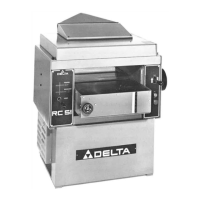
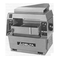
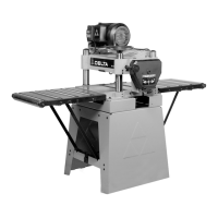
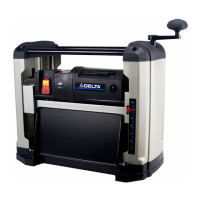
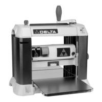
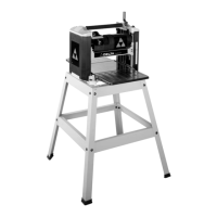
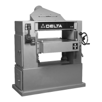
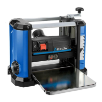
This document is an instruction manual for a Delta 20" Planer, Model RC-51. The manual provides comprehensive guidance on the operation, adjustment, and maintenance of the planer, ensuring safe and efficient use.
The primary function of the Delta 20" Planer is to reduce the thickness of wood stock and create smooth, parallel surfaces. It achieves this by passing wood through a cutterhead equipped with sharp knives, removing a precise amount of material with each pass. The planer is designed for woodworking applications, making it suitable for both professional workshops and serious hobbyists.
Usage Features:
The planer incorporates several features to enhance its usability and precision.
- On/Off Controls: The machine is started by pressing a green "ON" button and stopped by pushing a red "OFF" button. This simple control mechanism ensures straightforward operation.
- Table Raising and Lowering: The table height can be adjusted for different stock thicknesses. For rapid changes, a control lever allows quick raising or lowering. Fine adjustments are made using a handwheel after loosening a lock knob. The table height setting is indicated by an English/Metric scale. A unique feature is a shelf on the front of the table, which allows users to quickly determine stock thickness before or after planing, aiding in setting the table for the next cut. It's important to always raise the table to the desired setting, rather than lowering it, to remove any backlash from the screws.
- Feed Roll Speeds: The planer offers multiple feed roll speeds, which vary depending on whether it's a single-phase or three-phase machine. For single-phase models, speeds are 16 and 28 feet per minute (FPM), while three-phase models offer 25 and 46 FPM. A feed roll engagement lever allows users to engage or disengage the feed rolls. To change speeds, the engagement lever must be disengaged, and the drive belt repositioned on different steps of the motor and gearbox pulleys.
- Table Rollers: Two table rollers are provided to assist in feeding stock by reducing friction. The height of these rollers can be adjusted using a knob. For rough stock, the rollers should be set "HIGH," and for smooth stock, they should be set "LOW." This flexibility accommodates various wood types and planing needs.
- Anti-Kickback Fingers: To prevent kickback, the planer is equipped with anti-kickback fingers. These gravity-operated fingers ensure that wood only moves in the intended direction, enhancing operator safety. Regular inspection is recommended to ensure they move freely and are not obstructed by gum or pitch.
- Chipbreakers: Located above the cutterhead, chipbreakers help "break or curl" chips as stock is fed through, similar to a plane iron cap. They must be parallel to the knives and set slightly below the cutting circle to function effectively.
- Pressure Bar: Positioned directly behind the cutterhead, the pressure bar presses the stock down onto the table, ensuring consistent planing. It must be parallel to the knives and set slightly below the cutting circle.
- Outfeed Roller: The outfeed roll helps guide the planed stock out of the machine. Its setting is crucial for a smooth finish and is typically pre-set at the factory.
Maintenance Features:
The manual emphasizes several maintenance procedures to ensure the planer's longevity and optimal performance.
- Unpacking and Cleaning: Upon unpacking, the planer requires thorough cleaning to remove protective coatings from various components like the table, bed rollers, infeed roller, anti-kickback fingers, cutterhead, and knives. Kerosene is recommended for this task, with a strict warning against using gasoline, acetone, or lacquer thinner. Extreme care is advised when cleaning the cutterhead due to the sharpness of the knives. After cleaning, the table surface should be waxed.
- Drive Belt Tension Adjustment: Proper tension of the drive belts is crucial for efficient power transmission. The manual details how to check for 1/4" deflection with light finger pressure and adjust tension by loosening hex nuts and moving the motor plate.
- Feed Roll Belt Tension Adjustment: Similar to the drive belts, the feed roll belt tension needs to be maintained. A 1" deflection with light finger pressure is the target. Adjustment involves changing the position of a rod in a stud by tightening and loosening nuts.
- Knife Checking, Adjusting, and Replacing: This is a critical maintenance task. The manual provides detailed steps for checking knife settings using a knife gauge, adjusting them by loosening and tightening locking screws, and replacing them when dull or damaged. It stresses the importance of thoroughly cleaning knife slots, bars, springs, and screws, and maintaining a 40-degree cutting angle when sharpening. All four knives must be set to just contact the bottom of the gauge.
- Spring Tension on Feed Rollers: The infeed and outfeed rollers operate under spring tension, which must be sufficient to feed stock uniformly without slipping but not so tight as to damage the board. Adjustments involve turning screws until they are flush with the casting for the infeed roll and a few turns below the casting surface for the outfeed roll.
- Chipbreaker Adjustment: The bottom of the chipbreakers must be parallel to the knives and set .011" below the cutting circle. Adjustment involves placing a gauge block and feeler gauge on the table, raising or lowering the table until the knife touches the feeler gauge, then moving the gauge block under the chipbreakers to ensure they just touch its top. Screws can then be loosened to move the chipbreaker bracket, and individual spring tension can be adjusted.
- Pressure Bar Adjustment: The pressure bar needs to be parallel to the knives and set .011" below the cutting circle. The adjustment procedure is similar to the chipbreakers, using a gauge block and feeler gauge. Locking nuts and adjusting nuts are used to set the height, and spring tension can also be adjusted.
- Outfeed Roller Adjustment: The outfeed roll is factory-set at .035" below the cutting circle. To check and adjust, a gauge block and feeler gauge are used. If adjustment is needed, a jam nut is loosened, and a collar is turned to achieve the correct height.
- Chip Deflector Adjustment: The chip deflector's edge should be between .040" and .080" away from the cutting circle. Adjustment involves removing the chip chute, placing a feeler gauge between the knife and the deflector, and loosening screws to move the deflector.
- Table Height Scale Adjustment: The table height scale indicates the distance from the table to the cutting circle. To adjust the pointer, a piece of wood is run partway through the planer, its thickness measured, and then screws are loosened to adjust the pointer.
- Bed Roll Height Adjustment: The bed rolls should be set between .002" and .004" above the table surface at their lowest position. This is checked using a straight edge and a feeler gauge, with adjustments made by turning a height adjustment knob.
- Leveling the Table: The table is factory-set parallel to the cutterhead. If planing a taper, the manual instructs checking knife settings first, then verifying table parallelism using a gauge block. If the head casting is not parallel, chain and sprocket covers are removed, and an idler sprocket assembly is adjusted by turning a sprocket by hand. This adjustment is described as very sensitive.
- Lubrication: The gearbox oil should be changed annually using extreme pressure gear oil. The manual identifies the drain plug, oil fill screw, and oil level indicator.
- Gage Block: A gage block is supplied with the planer, but instructions are provided for making one out of hardwood if necessary.
Throughout the manual, a strong emphasis is placed on safety, with repeated warnings to disconnect the machine from the power source before performing any adjustments or maintenance. The use of safety glasses and proper grounding are also highlighted.