Do you have a question about the Delta ShopMaster TP400LS and is the answer not in the manual?
Read manual, wear PPE, proper apparel, and work in safe environments.
Instructions for using the on/off switch and locking the switch for safety.
Guides for adjusting depth of cut and setting the thickness scale.
Detailed steps for removing and installing new or reversed planer knives.
Completing knife replacement, reattaching the cutterhead guard, and securing screws.
Simple steps for achieving optimal planing results, including face truing and thicknessing.
Guidelines for checking and replacing motor brushes based on usage.
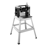
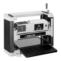
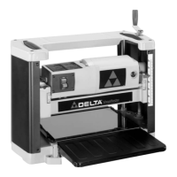
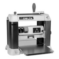
The DELTA ShopMaster Model TP400LS is a 12½" (317mm) Portable Planer designed for woodworking tasks, capable of handling workpieces up to 12½" (317mm) wide and 6" (152mm) thick. This machine is equipped with a powerful 15 amp, 120 volt motor, a two-knife cutterhead with double-edged reversible knives, and comes with a knife-installation tool, a stand, and a wrench.
The primary function of this portable planer is to reduce the thickness of wood stock and create flat, parallel surfaces. It achieves this by feeding a workpiece through a rotating cutterhead equipped with sharp knives, which shave off thin layers of wood. The depth of cut can be precisely controlled, allowing users to achieve desired workpiece thicknesses.
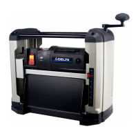
The planer is designed for ease of use and portability. It includes a foam-covered carrying handle located on top of the machine, which facilitates easy transportation. Additionally, carrying handles are provided at the base on each side, allowing for comfortable lifting. This top carrying handle also serves a dual purpose as a stock transfer bar, enabling users to easily move stock from the outfeed to the infeed end of the machine, which is particularly helpful when planing long materials and requiring multiple passes.
The machine features a cutterhead raising and lowering handle, which controls the depth of cut. One full revolution of this handle adjusts the cutterhead up or down by 3/32 of an inch. For optimal performance and safety, the cutterhead must always be locked in place by rotating the cutterhead lock handle clockwise before planing.
A dual English/Metric scale and a pointer are conveniently located on the front of the machine to indicate the thickness of the finished workpiece. The pointer can be adjusted by loosening two screws, setting the pointer, and then tightening the screws, ensuring accurate thickness readings.
Before operating the planer, it is crucial to ensure it is completely assembled and installed according to the instructions provided in the manual. The machine should be secured to a supporting surface to prevent sliding, walking, or tipping over during operation.
The on/off switch is located on the front of the planer motor. To turn the machine "ON," the switch is moved up, and to turn it "OFF," it is moved down. For safety, especially when the tool is not in use, the switch can be locked in the "OFF" position to prevent unauthorized use. This is achieved by grasping and pulling out the switch toggle. With the toggle removed, the switch will not operate. If the toggle is removed while the machine is running, the switch can be turned "OFF" but cannot be restarted without reinserting the toggle.
The infeed and outfeed table extensions are shipped in the "UP" position and must be rotated to the down position before use. It is essential that the top surface of these table extensions is level with the planer table. Adjustments can be made by loosening locknuts and adjusting stop screws on each end of the table extensions until they are level with the planer table, then tightening the locknuts. If necessary, two additional screws can be loosened, the table extension adjusted, and then tightened.
Recommended depths of cut vary based on wood type and width. For softwoods up to 8" wide, a maximum depth of cut of 3/32" is recommended. For hardwoods up to 7" wide, a maximum depth of cut of 3/32" is also recommended. For wider stock (10" and 12" wide), the recommended maximum depth of cut is 1/16" for softwoods and 3/64" for hardwoods. It is important to allow the cutterhead to reach full speed before feeding a workpiece to prevent kickback. Workpieces should always be fed against the direction of the cutterhead's rotation.
When planing bowed stock, the concave side of the stock should be placed down on the table and cut with the grain to prevent kickback. It is advised not to feed warped, knotty, or foreign object-embedded stock into the machine, as this can also cause kickback. Short, thin, or narrow workpieces should also be avoided to prevent hands from being drawn into the knives or the workpiece being thrown.
For best results, users should first true up one face of the board using a jointer, making thin cuts until the entire surface is flat. Then, the surfaced side should be placed face down and fed through the planer. Both sides of the board should be planed alternately with thin cuts until the desired thickness is achieved. If twisting, warping, or bowing occurs, the board should be trued up again. When planing long stock, table extensions should be used to support both the infeed and outfeed ends. Always engage the cutterhead lock before planing, plane with the grain only, and keep the planer table clean. Occasionally waxing the table surface can reduce friction. Finally, cross-cutting lumber to its final length after planing can remove any snipe that may have occurred. To ensure even wear of the knives, wood should be fed through different spots on the table when possible.
Regular maintenance is essential for the longevity and safe operation of the planer.
Knife Replacement: The planer knives are double-edged and reversible. To change them, first disconnect the machine from the power source. Raise the head assembly to its highest position. Remove the two screws securing the cutterhead guard and pull the guard straight out. The manual illustrates the cutterhead guard removed, exposing the cutterhead. Using the supplied wrench, insert it into the hex hole to rotate the cutterhead until the cutterhead lock engages and locks it in place. Then, using the wrench, unscrew the six screws (five of which are shown in the illustration) just enough for the locking bar to separate from the knife. The knife transfer tool, which is magnetized, can then be inserted underneath the center of the knife, lifted until the knife separates from its pins, and pulled out. To install a new knife or reverse an old one, position the knife transfer tool on top of the knife with the bevel up. Place the knife in the cutterhead underneath the locking bar, ensuring the pins in the cutterhead engage with the holes in the knife. Remove the knife transfer tool and tighten the six screws. This process should be repeated for the other knife by rotating the head 180 degrees. After replacing the knives, the cutterhead guard should be reinstalled, ensuring the cutterhead lock is depressed and underneath the guard, then sliding the guard in and replacing the two screws.
Outfeed Roller Height Adjustment: The outfeed roller is factory-adjusted to be 0.020" below the cutting circle. To check and adjust this, a homemade hardwood gage block (with specific dimensions provided in the manual) is needed. Disconnect the machine from the power source. Place the gage block on the table, over a 0.020" feeler gage, directly underneath the cutterhead. Raise or lower the head assembly and rotate the cutterhead until one of the knives just touches the top of the gage block when the knife is at its lowest point. Then tighten the cutterhead lock handle. Next, move the gage block (without the feeler gage) under one end of the outfeed roller. The bottom of the outfeed roller should just touch the top of the gage block. If adjustment is needed, loosen the locknut and turn the adjusting screw until the outfeed roller just touches the gage block, then tighten the locknut. This adjustment should be repeated for the opposite end of the outfeed roller.
Brush Inspection and Replacement: Brush life varies depending on motor load. For a new machine or after installing new brushes, inspect them after the first 50 hours of use, and then every 10 hours until replacement is necessary. Disconnect the machine from the power source before inspection. The brush holders are located on the motor housing. If the carbon on either brush is worn to 3/16" in length, or if the spring or shunt wire is burned or damaged, both brushes must be replaced. If serviceable, reinstall them in the same position.
Lubrication: The gears in the gear box and the feed roller bushings require periodic lubrication. Disconnect the machine from the power source. Remove the two screws on the bottom of the left side cover of the planer and remove the cover. Apply extreme pressure lithium grease to the teeth of the gears, then replace the side cover. Lay the planer on its back and squirt oil on the feed roller bushings at each end of the feed rollers.
Storage: The knife transfer tool can be stored underneath the outfeed table extension using a provided Velcro strip. The wrench can be stored in a designated hole located on the right rear side of the machine.
| Model | TP400LS |
|---|---|
| Motor | 15 Amp |
| Maximum Cutting Depth | 1/8 inch |
| Feed Rate | 26 feet per minute |
| Cutterhead Speed | 10, 000 RPM |
| Number of Blades | 2 |
| Type | Planer |
| Planing Width | 13 in. |
| Planing Depth | 0 - 1/8 in. |
| Cutterhead Diameter | 2 inches |
| Dust Port Size | 4 in. |