Do you have a question about the Delta TP305 and is the answer not in the manual?
Explains safety alert symbols like DANGER, WARNING, and CAUTION.
Warns about potential health risks from dust and chemicals in California.
Lists 24 essential safety practices for operating the machine.
Provides 23 safety rules specific to the operation of this portable planer.
Details safe electrical hookup, extension cord use, and grounding requirements.
How to operate the on/off switch and secure it to prevent unauthorized use.
Detailed instructions for safely removing and installing planer knives.
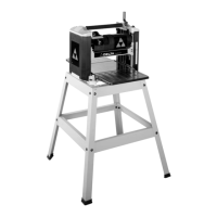
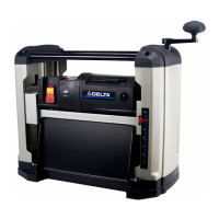
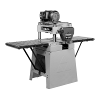
The Delta ShopMaster Model TP305 is a 12½" (317mm) Portable Planer designed for woodworking tasks, capable of handling workpieces up to 12½" (317mm) wide and 6" (152mm) thick. Its primary function is to plane wood to a desired thickness, making surfaces flat and smooth. The maximum depth of cut is 3/32" (2.4 mm), allowing for efficient material removal. The planer is equipped with a powerful 15 amp, 120 volt motor, ensuring robust performance for various wood types. A key feature of this planer is its two-knife cutterhead, which utilizes double-edged reversible knives. This design extends the life of the knives, as they can be flipped to use a fresh edge when one becomes dull or chipped. A knife-installation tool and wrench are included to facilitate knife replacement.
For safe operation, the planer must be completely assembled and installed according to the instructions provided in the manual. Before connecting the machine to a power source, it is crucial to ensure that the switch is in the "OFF" position. The machine must also be properly grounded to protect the operator from electric shock. The manual emphasizes the importance of using certified safety equipment, including eye protection (ANSI Z87.1 compliant), hearing protection (ANSI S3.19 compliant), and a dust mask (MSHA/NIOSH certified respirator) to guard against splinters, airborne debris, and dust. Proper apparel, such as non-slip footwear and protective hair covering, is also recommended to prevent entanglement with moving parts. Loose clothing, gloves, neckties, rings, bracelets, or other jewelry should be avoided.
The planer should not be operated in damp or wet environments or in the rain, as this can lead to electric shock. The work area must be well-lit to prevent accidents. Maintaining the machine in peak condition involves keeping tools sharp and clean, and following instructions for lubricating and changing accessories. Before each use, a thorough check for damaged parts, alignment of moving parts, binding, and breakage is necessary. Any damaged parts must be properly repaired or replaced. The work area should be kept clean and free of clutter. Children and visitors should be kept away from the workshop, which is considered a potentially dangerous environment.
To prevent unintentional starting, the switch must be in the "OFF" position before plugging in the power cord. In case of a power failure, the switch should also be moved to the "OFF" position. The machine is equipped with guards that must be in place, secured, and working correctly. Adjusting keys and wrenches must be removed from the machine before starting it to prevent them from being thrown at high speed. The planer should only be used for its intended purpose; forcing it to do a job for which it was not designed can result in damage or injury. Only accessories and attachments recommended by Delta should be used.
Proper extension cords are essential for safe operation. The manual specifies using a 3-wire extension cord with a 3-prong grounding type plug and matching receptacle. The cord must be heavy enough to carry the current the product will draw; an undersized cord can cause a drop in line voltage and overheating. A chart is provided to determine the correct gauge based on cord length and ampere rating. The workpiece should always be secured with clamps or a vise when practical to prevent loss of control. When feeding the workpiece, it must be moved against the direction of the rotation of the blade, cutter, or abrasive surface; feeding it from the opposite direction can cause kickback. The workpiece should not be forced into the machine. Operators should avoid overreaching to maintain balance and prevent contact with moving parts. Standing on the machine is prohibited.
The machine should never be left running unattended. The power must be turned OFF and the machine allowed to come to a complete stop before leaving it. Before installing or removing accessories, adjusting set-ups, or making repairs, the machine must be turned "OFF" and disconnected from the power source. To childproof the workshop, padlocks, master switches, or removal of starter keys are recommended. Operators must stay alert, watch what they are doing, and use common sense, avoiding operation when tired or under the influence of drugs, alcohol, or medication. Precautions against dust inhalation are crucial, as dust generated by certain woods can be injurious to health. Operating the machine in well-ventilated areas and using wood dust collection systems are advised.
Specific safety rules for planers include ensuring the machine is fully assembled before operation. Users unfamiliar with the machine should seek advice from a supervisor, instructor, or qualified person. All wiring codes and recommended electrical connections must be followed. Knives should be kept sharp, free from rust and pitch, as dull or rusted knives work harder and can cause kickback. The machine should never be turned "ON" before clearing the table of all objects. The workpiece should not contact the cutterhead when turning the machine "ON" to prevent kickback. The machine must be secured to a supporting surface to prevent sliding, walking, or tipping. Knives must be properly secured in the cutterhead before powering "ON." The speed setting must be locked securely before feeding the workpiece.
Awkward operations and hand positions should be avoided to prevent hands from moving into the knives. Arms, hands, and fingers must be kept away from the cutterhead, chip exhaust opening, and feed rollers. Reaching into the cutterhead area while the machine is running is strictly prohibited. Operators should not stand in line with the workpiece to avoid injury from kickback. The cutterhead must be allowed to reach full speed before feeding a workpiece. When planing bowed stock, the concave side should be placed on the table and cut with the grain. Warped stock, stock with knots, or embedded foreign objects should not be fed into the machine. Short, thin, or narrow workpieces should also be avoided, as hands can be drawn into the knives or the workpiece can be thrown at high speeds. Feeding a workpiece into the outfeed end of the machine will cause it to be thrown out at high speeds. Shavings should only be removed with the power "OFF." Long or wide workpieces must be properly supported. Layout, assembly, or set-up work should never be performed on the table/work area when the machine is running. Before leaving the machine, it should be turned "OFF," disconnected from the power source, and the table/work area cleaned. The switch should be locked in the "OFF" position to prevent unauthorized use.
The raising and lowering handle (A) Fig. 4 is attached to the shaft (B) and fastened with an M5x20mm screw (C), ensuring the flats of the handle and shaft are aligned. The handle is then flipped upward as shown in Fig. 5. The infeed and outfeed extension tables (A) Fig. 6 are shipped in a raised position and must be lowered. The top surface of the extension tables should be level with the planer table. To check and adjust, a straight edge (B) Fig. 14 is placed on the planer table (E) with one end extending over the infeed table (A). If adjustment is needed, the locknut (C) is loosened, and the stop screw (D) is adjusted until the extension table is level. The locknut (C) is then tightened. If necessary, the two screws (F) are loosened, the extension table adjusted, and the screws retightened. The outfeed table (G) is adjusted in the same manner. The knife transfer tool (A) Fig. 15 can be stored underneath the outfeed table extension (B) using a Velcro strip (C). The wrench (A) Fig. 16 can be stored in the hole (B) on the right rear side of the machine.
The cutterhead guard (A) Fig. 7 is attached by inserting its end over the top of the cutterhead and placing the slots (C) over the tapped holes (B). It is then fastened with two knobs, one of which is shown at (D) Fig. 8. The cutterhead guard must be properly secured before operating the machine. If the planer tends to tip, slide, or "walk" during operation, it must be secured to the supporting surface using the four provided holes (A) Fig. 9.
The on/off switch (A) Fig. 10 is on the front of the planer motor. Moving the switch up turns the machine "ON," and moving it down turns it "OFF." The switch must be in the "OFF" position before plugging in the power cord. In case of power failure, the switch must be moved to "OFF." To lock the switch, the switch toggle (D) Fig. 11 is pulled out. With the toggle removed, the switch will not operate. If the toggle is removed while the machine is running, it can be turned "OFF" but not restarted without re-inserting the toggle.
The head assembly (A) Fig. 12A contains the cutterhead, feed rollers, cutterhead guard, and motor. Rotating the handle (D) raises or lowers the head assembly, controlling the depth-of-cut. One revolution of the handle moves the cutterhead approximately 5/64" (2 mm). An English/metric scale and pointer (C) on the front of the planer indicates the cutterhead height. Adjustment to the pointer can be made by running a piece of wood through the machine, measuring its thickness, and then loosening two screws (B) to adjust the pointer. Continuous operation at the deepest depth of cut can cause premature motor failure.
For best results, the machine should be used as follows:
For knife replacement:
Maintenance features include keeping the machine clean by periodically blowing out air passages with dry compressed air. Plastic parts should be cleaned with a soft damp cloth, avoiding solvents that could damage the material. ANSI Z87.1 safety glasses should be worn when using compressed air. If the machine fails to start, check the cord plug for good contact and inspect for blown fuses or open circuit breakers.
Brush inspection and replacement are necessary. Brush life varies with motor load. For a new machine or after installing new brushes, check them after the first 50 hours of use, then every 10 hours until replacement is needed. The brush holders (A) Fig. 27 are on opposite sides of the motor housing. If the carbon (B) on either brush is worn to 3/16" in length, or if the spring (C) or shunt wire is burned or damaged, both brushes must be replaced. If serviceable, re-install them in the same position. After brush maintenance, the cutterhead guard must be re-installed before starting the planer.
Lubrication is required periodically for the gears in the gearbox and the feed roller bushings. Disconnect the machine from the power source before lubricating. Remove the screw (A) Fig. 29 and nut, then remove the side cover (B) from the left side of the planer. Apply a light coat of E.P. multi-purpose grease to the gear teeth (C) Fig. 30 and a light coat of spray lubricant to the chains (F). Replace the side cover. Place the planer on its back and squirt oil on the feed roller bushings (D) Fig. 31 at each end of the feed rollers (E).
| Model | TP305 |
|---|---|
| Max Planing Width | 13 inches |
| Cutterhead Speed | 10, 000 RPM |
| Feed Rate | 26 FPM |
| Dust Port Size | 4 inches |
| Type | Planer |
| Planing Depth | 1/8 inch per pass |