10
C
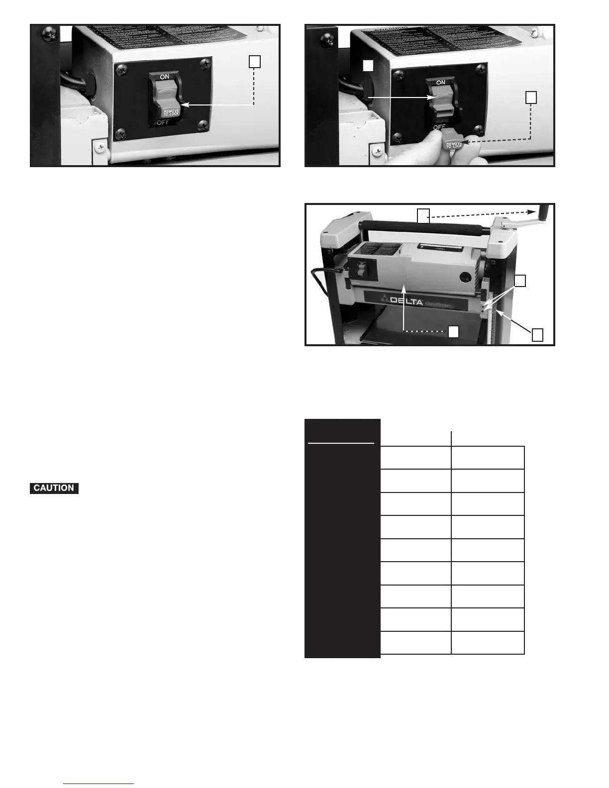
Fig. 10
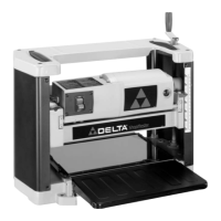
Fig. 11
A
A
D
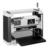
Fig. 12A
RAISING AND LOWERING HEAD
ASSEMBLY
The head assembly (A) Fig. 12A contains the cutterhead
feed rollers, cutterhead guard and motor. Raising and
lowering the head assembly controls the depth-of-cut
on your planer. To raise or lower the head assembly,
rotate the handle (D).
NOTE: One revolution of the handle will move the
cutterhead up or down approximately 5/64" (2 mm).
An English/metric scale and pointer (C) is located on the
front of the planer to indicate the height of the
cutterhead. Adjustment to the pointer can be made by
running a piece of wood through the machine. Measure
the thickness of the workpiece and if an adjustment is
necessary, loosen two screws (B) and adjust pointer
accordingly. Then tighten two screws.
Refer to Fig. 12B for recommended maximum depth-of-
cut for various board widths of soft and hard woods.
CONTINUOUS OPERATION AT THE
DEEPEST DEPTH OF CUT CAN CAUSE
PREMATURE MOTOR FAILURE.
A
C
D
Maximum depth-of-cut
Soft woods Hard Woods
2” (50.8 mm)
3/32” (2.4 mm) 3/32” (2.4 mm)
4” (101.6 mm) 3/32” (2.4 mm) 3/32” (2.4 mm)
6” (152.4 mm) 3/32” (2.4 mm) 3/32” (2.4 mm)
7” (177.8 mm) 3/32” (2.4 mm) 3/32” (2.4 mm)
8” (203.2 mm) 3/32” (2.4 mm) 5/64” (2 mm)
9” (228.6 mm) 5/64” (2 mm) 1/16” (1.5 mm)
10” (254 mm) 1/16” (1.6 mm) 3/64” (1.2 mm)
11” (279.4 mm) 1/16” (1.6 mm) 3/64” (1.2 mm)
12” (304.8 mm) 1/16” (1.6 mm) 3/64” (1.2 mm)
Board Width
Fig. 12B
B