EasyManua.ls Logo

Delta 22-681 - User Manual

Delta 22-681
24 pages
Print Icon
To Next Page IconTo Next Page
Loading...
INSTRUCTION MANUAL
DC-380 15" Planer
(Model 22-680, Single Phase)
(Model 22-681, Three Phase)
PART NO. 1346996 - 07-30-04
Copyright © 2004 Delta Machinery
To learn more about DELTA MACHINERY
visit our website at: www.deltamachinery.com.
For Parts, Service, Warranty or other Assistance,
please call
1-800-223-7278 (In Canada call 1-800-463-3582).
Shown with Delta
Model 50-654 Accessory
Planer Stand and
Roller Extension Tables
Question and Answer IconNeed help?

Do you have a question about the Delta 22-681 and is the answer not in the manual?

Overview

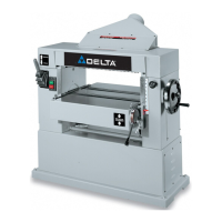
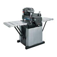
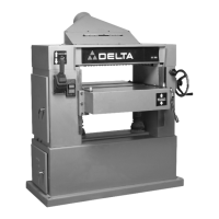
The DELTA DC-380 15" Planer (Model 22-680, Single Phase; Model 22-681, Three Phase) is a woodworking machine designed for planing wood stock to a desired thickness and achieving smooth surfaces. It features an adjustable feed rate for optimum planing under load.

Function Description:

The planer's primary function is to reduce the thickness of wood stock and create flat, smooth surfaces. It achieves this by passing the workpiece under a rotating cutterhead equipped with sharp knives. The depth of cut is adjustable, allowing for precise material removal. The machine also incorporates infeed and outfeed rollers to guide the workpiece, and anti-kickback fingers to enhance safety during operation. Two feed roll speeds are provided to accommodate different planing needs, from general planing to achieving a finer finish.

Important Technical Specifications:

  • Model Numbers: 22-680 (Single Phase), 22-681 (Three Phase)
  • Planing Width: 15 inches (381mm)
  • Planing Thickness: 6 1/2 inches (165mm)
  • Depth of Cut: 1/8 inch (5mm) maximum. A limiter is provided to restrict the depth of cut to 1/8" on stock wider than 6 inches. For stock narrower than 6 inches, the maximum depth of cut is 3/16" when run on one side or the other of the cutterhead.
  • Motor: Three horsepower, available in single phase (230 Volt) or three phase (200-220 Volt).
  • Feed Speeds: Two selectable speeds: 16 feet per minute and 30 feet per minute.
  • Electrical Circuit: Requires a separate electrical circuit, not less than #12 wire, protected with a 20 Amp time lag fuse.
  • Grounding: Must be grounded while in use to protect the operator from electric shock. Single phase machines use a 3-prong grounding type plug. Three phase machines must be permanently connected to the building electrical system and grounded according to the National Electrical Code.
  • Overload Protection (Three Phase Machine Only): The three-phase machine includes overload protection that will shut off the motor if overloaded or if line voltage falls below safe levels. The overload block automatically resets after cooling.

Usage Features:

  • Starting and Stopping:
    • Single Phase: On-off push button switch located on the motor junction box. "ON" is the start button, "OFF" is the stop button.
    • Three Phase: Switch located on the left front side of the planer head assembly. "ON" is the start button, "OFF" is the stop button.
  • Locking Switch: The switch can be locked in the "OFF" position using a padlock with a 3/16" diameter shackle to prevent unauthorized use. This is also recommended during power outages.
  • Depth of Cut Adjustment: Controlled by raising or lowering the head assembly using the head raising and lowering handwheel. Two head assembly lock knobs must be loosened before adjustment and tightened afterward.
  • Feed Speed Control: A shifter knob allows selection between 16 and 30 feet per minute. Pushing the knob all the way in sets the speed to 30 FPM, pulling it all the way out sets it to 16 FPM. A neutral (center) position stops feeding. Speed changes should only be made while the motor is running, not while planing.
  • Anti-Kickback Fingers: Located on the infeed end, these gravity-operated fingers prevent workpiece kickback. They require occasional inspection to ensure they are free of gum and pitch and operate correctly.
  • Table Rollers: Two table rollers aid in feeding stock by reducing friction. Their height is adjustable: HIGH (0.003" to 0.005" above table surface) for rough stock, and LOW (0.001" above table surface or level) for finish stock. Adjustment involves loosening set screws and turning eccentric screws, ensuring rollers remain parallel to the table.
  • Planing Techniques:
    1. True Up One Face: Feed one face over a jointer until flat.
    2. Plane to Thickness: Place the surfaced side face down and plane until flat. Alternate planing sides with thin cuts until desired thickness is achieved. If twisting or warping occurs, repeat step 1.
    3. Long Stock: Use table extensions for support.
    4. Best Results: Engage cutterhead lock before planing, plane with the grain, and keep the table clean and waxed.
    5. Cross-cut: Cross-cut lumber to final length.
  • Even Knife Wear: Feed wood through different spots on the table to prevent uneven wear of the knives.

Maintenance Features:

  • Cleaning: Periodically blow out air passages with dry compressed air. Clean plastic parts with a soft, damp cloth (avoid solvents).
  • Rust Protection: Cast iron tables should be cleaned and protected from rust using WD-40®, degreaser, and TopCote® Aerosol, applied with a Scotch-Brite™ Blending Hand Pad and a pushblock.
  • Lubrication:
    • Gear Box Oil: Change annually using extreme pressure gear oil (approx. 20 oz.). Drain plug is at the bottom, fill and level plug is on the side.
    • Raising Screws: Lubricate periodically with common grease.
    • Chains and Sprockets: Periodically clean and lubricate with light (10W) machine oil. Access by removing the side cover.
    • Feed Roller Bushings: Periodically squirt light (10W) machine oil on bushings at each end of the feed rollers.
  • Infeed and Outfeed Rollers Cleaning: Clean periodically with soap, water, and a Scotch-Brite™ pad.
  • Knife Maintenance (Checking, Adjusting, Replacing):
    • Safety: Disconnect power source before any knife maintenance. Cutterhead and knives are sharp; exercise extreme care.
    • Removal: Remove top cover and chip deflector. Loosen locking screws to remove knives and locking bars.
    • Cleaning: Thoroughly clean knives, knife slots, locking bars, and screws. Replace worn or stripped screws.
    • Adjustment: Use a knife setting gage to ensure knives just contact the bottom of the gage at each end. Loosen locking screws, adjust the knife height using the allen screw, then lightly snug locking screws. Once all knives are set, securely tighten all five locking screws, starting with end screws.
  • Chipbreaker Height Adjustment:
    • Safety: Disconnect power source.
    • Procedure: Ensure knives are properly adjusted. Place a gage block with a 0.020" feeler gage under the cutterhead, raise/lower head until a knife touches the feeler gage. Lock the head. Place the gage block (without feeler gage) under one end of the chipbreaker; it should just touch the block. Adjust chipbreaker height by loosening a nut and turning an adjusting screw. Repeat for the other end.
  • Infeed Roller Height Adjustment:
    • Safety: Disconnect power source.
    • Procedure: Ensure knives are properly adjusted. Place a gage block with a 0.040" feeler gage under the cutterhead, raise/lower head until a knife touches the feeler gage. Lock the head. Move the gage block (without feeler gage) under one end of the infeed roller; it should just touch the block. Adjust infeed roller height by loosening a nut and turning an adjusting screw. Repeat for the other end.
  • Outfeed Roller Height Adjustment:
    • Safety: Disconnect power source.
    • Procedure: Ensure knives are properly adjusted. Place a gage block with a 0.040" feeler gage under the cutterhead, raise/lower head until a knife touches the feeler gage. Lock the head. Move the gage block (without feeler gage) under one end of the outfeed roller; it should just touch the block. Adjust outfeed roller height by loosening a nut and turning an adjusting screw. Repeat for the other end.
  • Cuttinghead Parallel to Table Adjustment:
    • Safety: Disconnect power source.
    • Procedure: Place a gage block under the front edge of the head casting on the table. Lower the head until it touches the block. Move the gage block to the opposite end; distance should be the same. Repeat for the outfeed end. If not parallel, tilt the planer on its side. Remove one bolt and loosen another on the idler sprocket assembly to release chain tension. Remove the chain from the sprocket on the end needing adjustment. Turn the sprocket by hand (clockwise decreases distance, counterclockwise increases distance) in small increments (one or two teeth). Replace chain and idler sprocket assembly.
  • Constructing Gage Block: A homemade hard wood gage block is needed for various adjustments. Dimensions are provided in the manual.

Accessory:

  • 50-314 Stand: An optional accessory stand for the planer. Assembly involves carriage bolts, flat washers, lockwashers, and nuts. The planer is mounted to the top shelf of the stand. Lifting the heavy planer onto the stand requires a minimum of four people and specific positioning using 2x4s.

Delta 22-681 Specifications

General IconGeneral
BrandDelta
Model22-681
CategoryPlaner
LanguageEnglish

Related product manuals