8
Use proper extension cords. Make sure your extension
cord is in good condition and is a 3-wire extension cord
which has a 3-prong grounding type plug and a 3-hole
receptacle which will accept the tool’s plug. When using
an extension cord, be sure to use one heavy enough to
carry the current of the tool. An undersized cord will
cause a drop in line voltage, resulting in loss of power
and overheating. Fig. 13, shows the correct gauge to
use depending on the cord length. If in doubt, use the
next heavier gauge. The smaller the gauge number, the
heavier the cord.
EXTENSION CORDS
Fig. 13
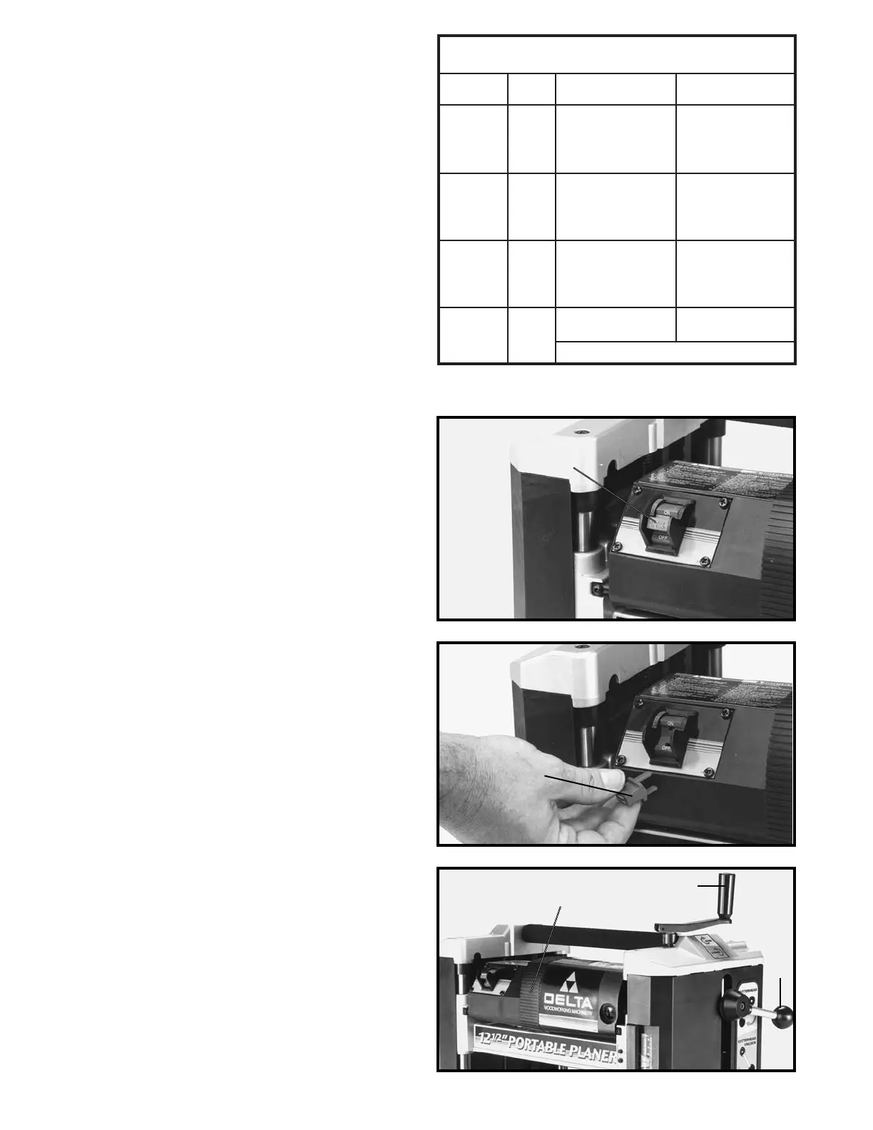
MINIMUM GAUGE EXTENSION CORD
RECOMMENDED SIZES FOR USE WITH STATIONARY ELECTRIC TOOLS
Ampere Total Length Gauge of
Rating Volts of Cord in Feet Extension Cord
0-6 120
up to
25 18 AWG
0-6 120 25-50 16 AWG
0-6 120 50-100 16 AWG
0-6 120 100-150 14 AWG
6-10 120
up to
25 18 AWG
6-10 120 25-50 16 AWG
6-10 120 50-100 14 AWG
6-10 120 100-150 12 AWG
10-12 120
up to
25 16 AWG
10-12 120 25-50 16 AWG
10-12 120 50-100 14 AWG
10-12 120 100-150 12 AWG
12-16 120
up to
25 14 AWG
12-16 120 25-50 12 AWG
12-16 120
GREATER THAN 50 FEET NOT RECOMMENDED
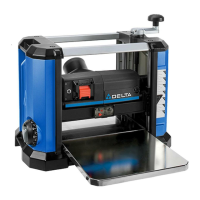
STARTING AND
STOPPING PLANER
The on/off switch (A) Fig. 14, is located on the front of
the planer motor. To turn the machine “ON” move the
switch to the up position. To turn the machine “OFF”
move the switch to the down position.
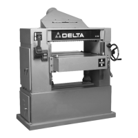
LOCKING SWITCH IN
THE “OFF” POSITION
When the tool is not in use, the switch should be locked
in the “OFF” position to prevent unauthorized use. This
can be done by grasping the switch toggle (B) Fig. 15,
and pulling it out of the switch, as shown. With the
switch toggle removed, the switch will not operate.
However, should the switch toggle be removed while the
machine is running, the switch can be turned “OFF”
once, but cannot be restarted without inserting the
switch toggle.
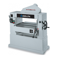
OPERATING CONTROLS AND ADJUSTMENTS
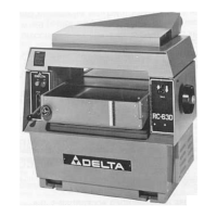
RAISING AND LOWERING
HEAD ASSEMBLY
The head assembly (A) Fig. 16, contains the cutterhead,
feed rollers, chip deflector and motor. Raising and
lowering the head assembly controls the depth of cut on
your planer. To raise or lower the head assembly, rotate
the cutterhead lock handle (B) counterclockwise to
unlock the cutterhead and turn the cutterhead raising and
lowering handle (C) clockwise to raise or
counterclockwise to lower the cutterhead. One revolution
of handle will move the cutterhead up or down 3/32". FOR
BEST RESULTS, ALWAYS LOCK THE CUTTERHEAD
IN PLACE, BY ROTATING HANDLE (B) CLOCKWISE
BEFORE PLANING.
Fig. 14
Fig. 15
Fig. 16
A
B
A
C
B